
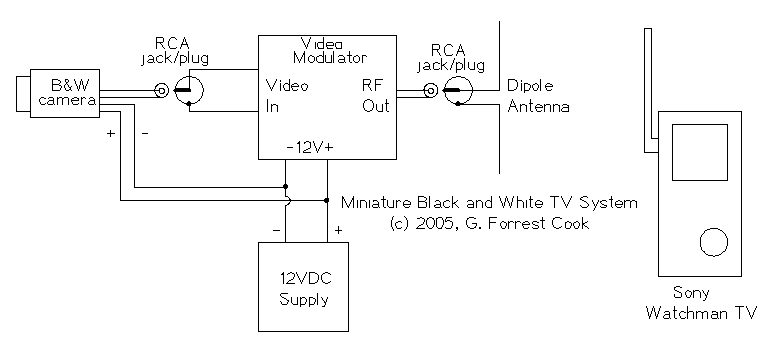
Miniature Black and White TV System
Turn the power for the camera and modulator on, turn on the TV. Tune the TV to the channel of the RF modulator, fine-tune the TV for the best picture. For full-time operation, use the appropriate AC adapter for the watchman. If battery operation is desired, run the TV from its internal batteries and use a 12V battery for powering the camera and modulator. A rechargeable lead acid battery with a series fuse (and a recharging circuit) is recommended. A fun use for this system would be to create an engineer's view of a model train layout. A loop of wire near the track would make a good receiving antenna. Power could be pulled from the engine motor circuit using a bridge rectifier feeding into an electrolytic capacitor, just make sure not to exceed the camera's 12V maximum supply voltage.
Parts
Miniature black and white video camera, 12VDC, Model PC-206XP Video modulator block, Jameco 141639CJ or equivalent Sony Watchman miniature TV 12V DC power supply, beware of wall-warts - they often have inaccurate voltage ratings. Miscellaneous wires and cables
The described circuit utilizes a 12VDC power supply to energize both the miniature black and white video camera (Model PC-206XP) and a video modulator. The output video signal from the camera is routed through an RCA jumper cable into the video input of the modulator. The modulator processes the video signal and outputs a modulated radio frequency (RF) signal, which is then transmitted via a small antenna. A dipole antenna, specifically tuned to the modulator's frequency, is recommended to enhance signal range and quality.
For short-range applications, the antenna can be constructed from two lengths of #16 gauge solid wire. In cases requiring longer distances, the RF output can be connected to a 75-ohm coaxial cable. It is essential to incorporate a 75-ohm terminating resistor at the far end of the coaxial cable to ensure proper signal integrity. The remote center conductor of the coax should be coupled to the TV antenna using a 330-ohm resistor to match impedance and minimize signal loss.
Operational guidelines include powering on the camera and modulator, followed by the television receiver. The TV should be tuned to the corresponding channel of the RF modulator, and fine-tuning may be necessary for optimal image clarity. For continuous use, an AC adapter compatible with the Sony Watchman is advisable. Alternatively, if battery operation is preferred, a 12V battery can power the camera and modulator, while the TV can operate on its internal batteries. A rechargeable lead-acid battery setup, equipped with a series fuse and a charging circuit, is recommended for safety and efficiency.
This system can serve various practical applications, such as providing a live view of a model train layout. A simple loop of wire placed near the track can function as an effective receiving antenna. Power can be sourced from the model train's engine motor circuit, utilizing a bridge rectifier and an electrolytic capacitor to ensure the voltage remains within the camera's maximum 12V threshold.
The components required for this setup include a miniature black and white video camera (Model PC-206XP), a video modulator block (such as the Jameco 141639CJ), a Sony Watchman miniature TV, a suitable 12V DC power supply, and various wires and cables for connections. Caution is advised when selecting the power supply, as many wall-wart adapters may not provide accurate voltage outputs.The 12VDC supply provides power for the camera and video modulator circuits. The video from the camera is fed into the video input of the modulator circuit. The modulated RF from the modulator is fed into a small antenna. Use of a dipole antenna that is resonant at the frequency of the modulator can extend the signal range. The RF travels across a short distance to the Sony Watchman TV receiver. A black and white image magically appears on the TV screen. The camera's video signal is connected to the video modulator with an RCA jumper cable. Power to the camera and video modulator is connected to the 12V power supply. Be careful with polarity, reversing the leads may damage the modulator. The camera that was used had reverse polarity protection built in. The modulator's RF output signal is connected to a small antenna, the antenna can be made with two short lengths of #16 gauge solid wire. Alternately, for long distance wired operation, the RF signal can be fed into a length of 75 ohm coax cable with a 75 ohm terminating resistor across the far end of the cable.
Connect the remote center conductor of the cable to the TV antenna through a 330 ohm resistor. Use Turn the power for the camera and modulator on, turn on the TV. Tune the TV to the channel of the RF modulator, fine-tune the TV for the best picture. For full-time operation, use the appropriate AC adapter for the watchman. If battery operation is desired, run the TV from its internal batteries and use a 12V battery for powering the camera and modulator. A rechargeable lead acid battery with a series fuse (and a recharging circuit) is recommended. A fun use for this system would be to create an engineer's view of a model train layout. A loop of wire near the track would make a good receiving antenna. Power could be pulled from the engine motor circuit using a bridge rectifier feeding into an electrolytic capacitor, just make sure not to exceed the camera's 12V maximum supply voltage.
Parts Miniature black and white video camera, 12VDC, Model PC-206XP Video modulator block, Jameco 141639CJ or equivalent Sony Watchman miniature TV 12V DC power supply, beware of wall-warts - they often have inaccurate voltage ratings. Miscellaneous wires and cables 🔗 External reference
Related Circuits
This audio amplifier circuit is designed for use in classrooms to alleviate the strain of lecturing in noisy environments. It incorporates the power amplifier IC LM380, which delivers an output of 2 watts, adequate for confined spaces. The amplifier...
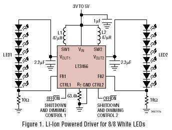
LT3466 is a dual full function step-up DC/DC converter specifically designed to drive up to 20 White LEDs (10 in series per converter) with a constant current. Series connection of the LEDs provides identical LED currents resulting in uniform...
This miniature transmitter is easy to construct and its transmissions can be picked up on any standard FM receiver. It has a range of up to 1/4 of a mile or more. It is great for room monitoring, baby...
The component is deformed due to various thermal influences during processing, which compromises the original machining accuracy and introduces errors. In precision finishing, the effect of thermal deformation is particularly significant, leading to processing errors that can exceed 40%....
The circuit provides sufficient illumination suitable for reading purposes. Capacitor CX, in conjunction with diodes D1 through D4, constitutes the AC step-down circuit. CX lowers the high voltage AC from the mains to a low voltage AC, which is...
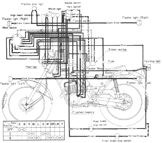
The following image illustrates the Yamaha 175 Wiring Diagram (CT2 and CT3 model) and Electrical System Schematic. It provides detailed information regarding the interconnection and wiring between electrical components of the motorcycle, including the battery, ground, headlight, taillight, horn,...