
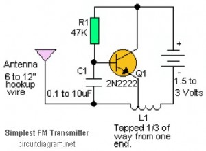
miniature fm transmitter

The described miniature FM transmitter circuit is designed for simplicity and versatility, making it suitable for various applications such as room monitoring, baby listening, and nature research. The core components include an inductor (L1), a trimmer capacitor (C4), and a basic oscillator circuit, which collectively enable transmission within the FM band.
L1, consisting of 8 to 10 turns of 22-gauge wire wound tightly around a non-conductive form, serves as the inductor. The choice of a non-conductive form, such as a pencil, is critical to avoid interference with the magnetic field generated by the coil. The winding should be close to ensure a compact and effective inductance value, which is essential for tuning the transmitter to the desired frequency.
C4, the screw-adjustable trimmer capacitor, plays a vital role in frequency modulation. It allows for fine-tuning of the oscillator frequency by adjusting the capacitance, which directly affects the resonant frequency of the LC circuit formed with L1. To achieve optimal performance, it is recommended to set the FM receiver to a clear frequency in the lower end of the FM band and then adjust C4 using a non-conductive tool to find the clearest reception.
The circuit's range of approximately 1/4 mile is dependent on several factors, including the power supply, antenna design, and environmental conditions. A simple wire antenna can be attached to the output of the transmitter to enhance the range and improve signal quality. The transmitter's non-critical component values allow for experimentation, enabling users to modify component values to observe variations in performance.
In conclusion, this miniature FM transmitter circuit is an accessible project for electronics enthusiasts, providing opportunities for experimentation and practical applications in monitoring and research. Proper construction and tuning are essential for achieving the best results, and users are encouraged to explore different configurations to optimize performance.This miniature transmitter is easy to construct and it`s transmissions can be picked up on any standard FM receiver. It has a range of up to 1/4 of a mile or more. It is great for room monitoring, baby listening, nature research, etc. L1 is 8 to 10 turns of 22 gauge hookup wire close wound around a non-conductive 1/4 inch diameter form, such as a pencil.
C4 is a small, screw-adjustable, trimmer capacitor. Set your FM receiver for a clear, blank space in the lower end of the band. Then, with a non-conductive tool, adjust this capacitor for the clearest reception. A little experimenting and patience may be in order. Most of the parts` values are not critical, so you can try adjusting them to see what happens. 🔗 External reference
Related Circuits
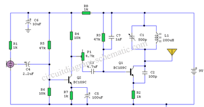
The AM transmitter circuit consists of an audio amplifier and an RF oscillator. The oscillator is constructed around transistor Q1 and its associated components. The tank circuit, which includes inductor L1 and variable capacitor VC1, is tunable from approximately...
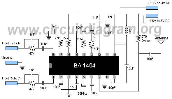
A high-quality FM stereo transmitter circuit schematic utilizing the BA1404 FM transmitter integrated circuit (IC). This circuit is straightforward to assemble, requiring only a few external components. The FM stereo transmitter circuit based on the BA1404 IC is designed to...
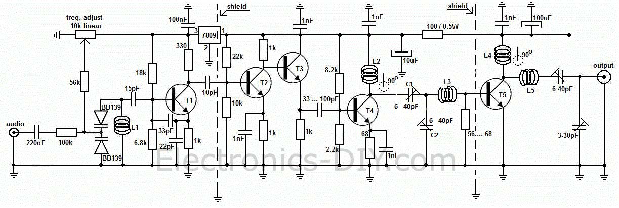
This circuit is a long-range, highly stable, harmonic-free FM transmitter designed for FM frequencies between 88 and 108 MHz. With an appropriate antenna, it can cover a range of up to 5 km. The circuit features a stable oscillator...
This is likely the simplest radio transmitter available, consisting of five components and capable of being assembled in a compact space. It is suitable for science fair projects or other science-related endeavors where short-range transmission is beneficial. The device...
Current loop analog data transmission is utilized in industrial environments due to its robustness, offering good noise immunity and the capability for wiring fault detection. Current loop analog data transmission systems are widely employed in industrial applications due to their...

The circuit is essentially a radio frequency (RF) oscillator that operates around 100 MHz. Audio signals captured and amplified by the electret microphone are directed into an audio amplifier stage constructed around the first transistor. The output from the...