
Xilinx ISE Schematics Sequential Circuit
The circuit design described involves creating a sequential logic circuit to control three LEDs based on the state of an external command signal. The LEDs will illuminate in a defined sequence, dictated by the states of the flip-flops used in the design. The primary component, an FD flip-flop, will serve as the memory element that retains the state of the circuit.
The sequential circuit will be structured using a finite state machine (FSM) approach, where each state corresponds to a specific LED being lit. The states can be defined as follows: State 0 (Red ON), State 1 (Green ON), State 2 (Yellow ON), and State 3 (both Q1 and Q0 are high, indicating a transient state). The control logic will ensure that when the command signal (cmd) is low (0), the system remains in State 3, lighting the red LED. If cmd is high (1) while the currently lit LED is not red, the FSM will transition through the sequence from green to yellow to red.
In terms of implementation, the circuit will require careful consideration of the timing and edge conditions. The flip-flops must be configured to respond to the clock signal appropriately, with attention to whether they are triggered on a rising or falling edge. The use of a preset input on the flip-flops will allow for manual intervention to force the states of Q1 and Q0 to 1, facilitating the transition to the desired state for testing purposes.
The synthesis process will be critical, as it will compile the Verilog code into a format suitable for the target FPGA. Successful synthesis will confirm that the design is free from errors and ready for further testing and deployment. The console's error log will serve as a valuable resource for diagnosing any issues that arise during this process.
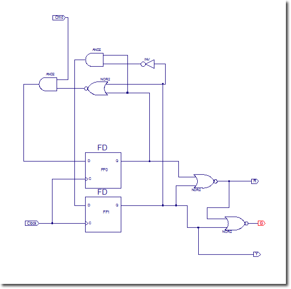
Overall, this lab provides a practical application of sequential circuits, demonstrating the functionality of flip-flops in controlling output devices such as LEDs based on defined input conditions. The design not only emphasizes the importance of state management in digital circuits but also highlights the role of simulation and synthesis in verifying circuit behavior.In this lab we will be using flip-flops. Xilinx offers a large library of sequential circuits. Make sure to check it out when searching for circuits: Xilinx Refernce Library. The circuit we want to implement in this lab is a sequential circuit controlling 3 LEDs, one Green, on Yellow, and one Red that stay on for one cycle of the clock in the fol lowing fashion: When the outside command cmd is 0, the cycling stops on Red. If cmd is activated when the light that is on is not Red, the cycling still follows the Green-Yellow-Red path, and stops on Red as long as cmd remains 0. Xilinx supports many different flip-flop models, some with active low signals, some with negative edge clocks.
You can find them all in the Xilinx Library Manual (in pdf form). We`ll pick the FD flip-flop for this lab: You can verify that a set of wires are connected properly by using cursor mode (you click on the cursor arrow in the vertical menu) and clicking on one of the wires. Every wire connected to that wire, including this wire, will turn red. Synthesize your circuit (in Impement Design menu of options). Continue only if your synthesis is successful. Otherwise figure out what the bugs are from the error log in the console window. Our design for this 3-state sequencer has a transient state. When Q1 and Q0 are 1 1, the system is in State 3, for which Yellow is 1, and it should automatically bring the FSM to State 0, where Red should be 1.
We cannot verify its correct behavior, unless we find a way to force Q1 and Q0 to 1. One way to do this is to modify the schematics and use different flip-flop designs that have a Preset input, and modify the Verilog test module to activate this Preset at the right times. 🔗 External reference
Related Circuits

This circuit is capable of delivering approximately 200W of power output, produced by Phillips Semiconductor. It utilizes two PHP1BN11QT devices and operates with an input voltage range of 30 to 45 Volts DC. The described circuit is a high-power switching...

This is a stereo amplifier circuit diagram. The amplifier will produce stereo output channels with a power audio output that can reach up to 70W for each channel. The amplifier is built using the STA550 chip from STMicroelectronics. It...
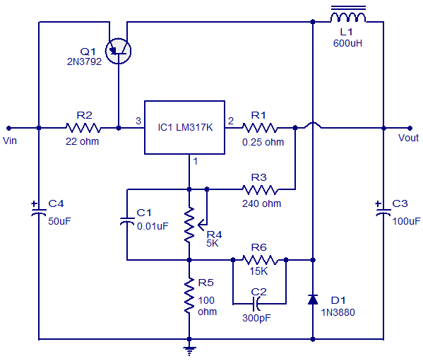
This circuit illustrates a 3A Switching Regulator Circuit based on the LM317K integrated circuit. It is designed to be simple and cost-effective. The 3A Switching Regulator Circuit utilizing the LM317K IC serves as a versatile voltage regulation solution, capable of...
Advanced power control systems utilize electronic components such as thyristors for power switching, motor control, and other applications. These systems are involved in inverter design, lamp dimming, and speed control of motors. Triacs are the most commonly used semiconductor...

One type of metal detector is a beat frequency oscillator (BFO). The operation of metal detectors relies on changing the characteristics of the oscillator when it is near a metal object detected by the sensor. The detector functions based...

The following circuit diagram depicts a 100 Watt audio power amplifier, constructed using the LM3886 power amplifier chip. A single LM3886 IC can amplify audio power output up to 68W. In this circuit, two LM3886 chips are configured in...