
Miniature Real-time Controller

The Miniature Real-time Controller is designed to manage multiple home appliances, including lighting and air conditioning, through a compact and efficient circuit. The core of the system is the 89C2051 microcontroller, which operates at a frequency of 3.579 MHz, utilizing a low-cost crystal oscillator for timing purposes. This microcontroller is programmed with firmware (timer6.hex) that enables it to handle scheduling tasks for the connected devices.
The circuit features a 6-channel output system, specifically utilizing pins P1.2 to P1.7 of the microcontroller. Each channel is capable of sinking a maximum current of 20 mA, making it suitable for interfacing with opto-triacs or solid-state relays that control larger loads, such as lights or HVAC systems. The opto-triac functions as an interface between the low-power control signals from the microcontroller and the high-power devices, ensuring safe operation.
To facilitate communication with a PC for scheduling, the circuit incorporates a serial communication chip, either the DS275 or the MAX232. This chip is responsible for converting the TTL-level signals from the microcontroller to RS-232 levels, which are compatible with most PCs. The scheduling information can be downloaded from a computer and stored in the on-chip RAM of the 89C2051, allowing for flexible and programmable control of the outputs.
The use of the 74LS07 open collector driver is crucial for driving the outputs, as it allows for the connection of multiple devices to a single output line while maintaining the ability to sink current effectively. This configuration ensures that the system can handle the demands of various home appliances without the risk of overloading the microcontroller.
In summary, the Miniature Real-time Controller is a versatile and efficient solution for home automation, capable of controlling multiple devices with a simple and effective circuit design. The integration of the microcontroller, communication interface, and output drivers creates a robust system suitable for a variety of applications in home management.This is my long history the device that controls my home`s night light, air-conditioner,etc. The device is a Miniature Real-time Controller. The circuit uses only three chips, a 89C2051, DS275(or MAX232), and 74LS07 open collector driver. The scheduler for time on/off of 6-channel output can be made by downloading from PC and saved into onchip RAM. Each output provides a 20mA sinking suitable for driving a homemade opto-triac or big solid-state relay for heavy load.
A circuit diagram of the Miniature Real-time Controller is shown in Figure 1. A 89C2051 with a low-cost X-tal 3.579MHz runs timer6.hex. The 6-channel output is P1.2 to P1.7 driving with sink current. A 74LS07 open collector provides approx. max 20mA @12V 🔗 External reference
Related Circuits
General Diagram of Motor Controller Manual PDF Download. The motor controller is an essential component in various applications, including robotics, electric vehicles, and industrial machinery. It regulates the operation of electric motors by controlling parameters such as speed, direction, and...
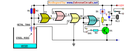
This circuit utilizes a relay to control a water pump for automatic level regulation of a water reservoir or well. The shorter steel rod acts as a high water sensor, while the longer rod serves as a low water...
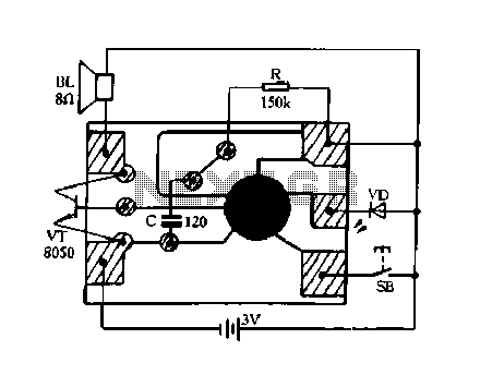
Constantly changing light and sound analog controller circuit 02 The circuit described is an analog controller designed to modulate light and sound in a dynamic manner. It typically utilizes components such as operational amplifiers, resistors, capacitors, and transistors to achieve...
.jpg)
This is a general-purpose remote control project utilizing programmable PIC microcontrollers (PIC16F628, PIC16F630, PIC16F684). Schematics are provided for using infrared (IR) or radio frequency (RF) media. For those unfamiliar with microcontroller programming, fixed encoder and decoder integrated circuits can...
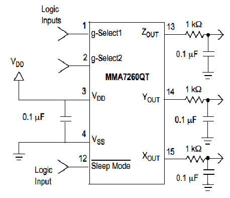
Microcontroller-Based Accelerometer Project. Just as a speedometer is a device that measures speed, an accelerometer is a device that measures acceleration. The microcontroller-based accelerometer project utilizes an accelerometer sensor to detect changes in velocity and orientation. This project typically involves...
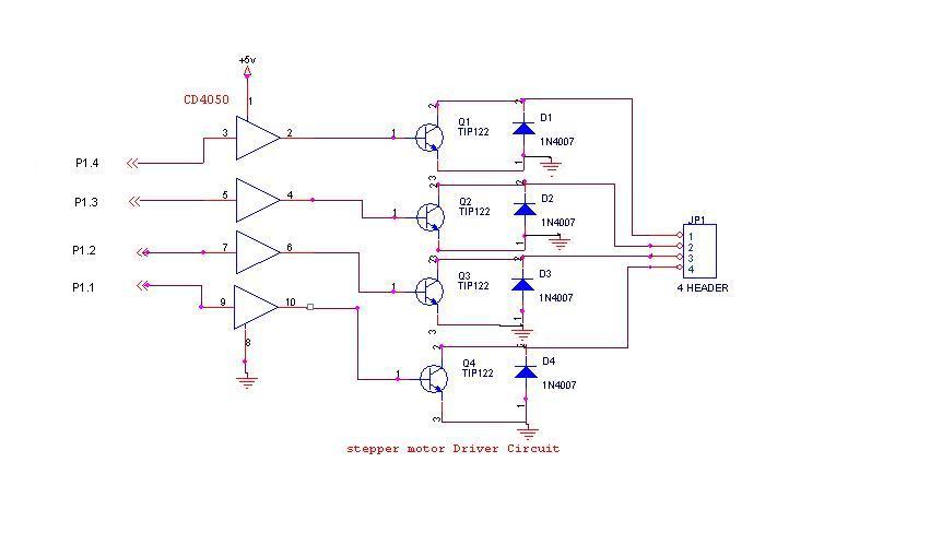
A 6V, 2A stepper motor is utilized in this circuit. The CD4050 hex buffer is employed to connect to the microcontroller. The output of the CD4050 is linked to the base of a TIP122 transistor. The emitter and collector...