
Water Pump Relay Controller Circuit Schematic
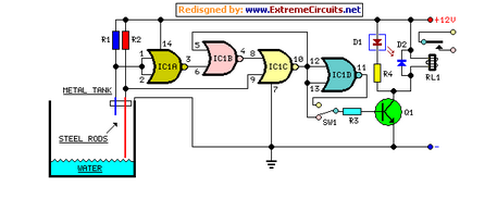
The circuit design employs a relay to control the operation of a water pump based on the water level detected by two sensors. The shorter sensor, positioned at the high water mark, and the longer sensor, at the low water mark, provide critical feedback to the integrated circuit (IC1C). The logic within IC1C determines the state of the pump based on the water level detected by these sensors.
Initially, when the water level is low, both sensors do not make contact with the water, resulting in a low output from IC1C. As water fills the reservoir, it first contacts the longer sensor, but the output remains low until the shorter sensor is activated. The transition of IC1C to a high output triggers Q1, which energizes the relay, activating the pump. This action begins to lower the water level in the reservoir.
While the pump operates, the water level will eventually drop below the shorter sensor, but the output of IC1C remains high due to the feedback from IC1B, allowing the pump to continue functioning until the water level reaches the longer sensor. At this point, the output of IC1C returns to low, signaling the pump to stop.
The inclusion of an optional switch, SW1, allows for versatility in operation. By connecting R3 to pin #11 of IC1D, the circuit can be reconfigured such that the pump operates in reverse. In this mode, the pump will start when the water level is low and stop when the reservoir is full, allowing for the filling of the reservoir instead of its emptying.
This configuration provides a reliable solution for automatic water level management, ensuring efficient operation of the pump while also allowing for flexibility in its intended use. The use of feedback mechanisms within the integrated circuits ensures that the system reacts appropriately to changes in water level, maintaining the desired operational parameters.By means of a Relay, employed to drive a water pump, this circuit provides automatic level control of a water reservoir or well. The shorter steel rod is the water high sensor, whereas the longer is the water low sensor. When the water level is below both sensors, IC1C output (pin #10) is low; if the water becomes in contact with the longer
sensor the output remains low until the shorter sensor is reached. At this point IC1C output goes high, Q1 conducts, the Relay is energized and the pump starts operating. Now, the water level begins to decrease and the shorter sensor will be no longer in contact with the water, but IC1C output will be hold high by the signal return to pin #5 of IC1B, so the pump will continue its operation.
But when the water level falls below the longer sensor, IC1C output goes low and the pump will stop. SW1 is optional and was added to provide reverse operation. Switching SW1 in order to connect R3 to pin #11 of IC1D, the pump will operate when the reservoir is nearly empty and will stop when the reservoir is full. In this case, the pump will be used to fill the reservoir and not to empty it as in the default operating mode.
🔗 External reference
Related Circuits
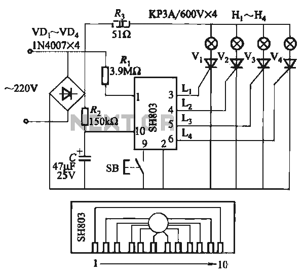
The circuit utilizes the SH803 flash IC, which can store eight different programs and offers various dimming options and light speed adjustments. A button is provided to trigger the control terminal SB on the 9-pin connector for program selection,...
Here is a simple schematic of a TV transmitter circuit, or video transmitter circuit, capable of broadcasting in the VHF range from 60 to 200 MHz. The input video source can be any CCD camera or VCR. The output...
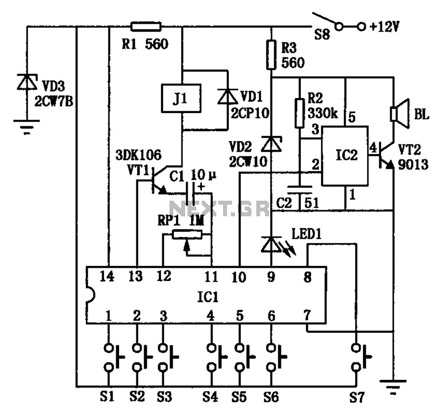
The automotive electronic locks circuit principle is illustrated with the dedicated lock IC 5G058. It features an external key switch connected to the positive power supply. The circuit includes six valid input keys, unlock keys S1 to S6, which...
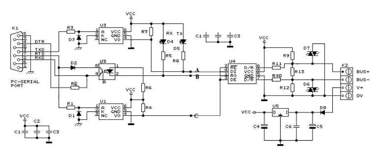
RS232 to RS485 Converter Circuit Schematic. RS232 to RS485 converters are primarily utilized in industrial and commercial settings. The RS232 to RS485 converter circuit is designed to facilitate communication between devices using different serial communication standards. RS232 is commonly found...
This quartz crystal oscillator circuit exhibits greater stability compared to a parallel resonance circuit. It is capable of generating frequencies up to 30 MHz or even higher when utilizing BFR91 transistors for T1 and T2, along with reduced values...
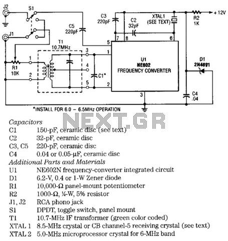
The NE602 chip, U1, contains oscillator and mixer stages. The mixer combines the oscillator signal with the input RF signal to produce signals whose frequencies are the sum and difference of the input frequencies. For example, an 8.5-MHz oscillator...