
Miniature Vacuum Tube Tesla Coil
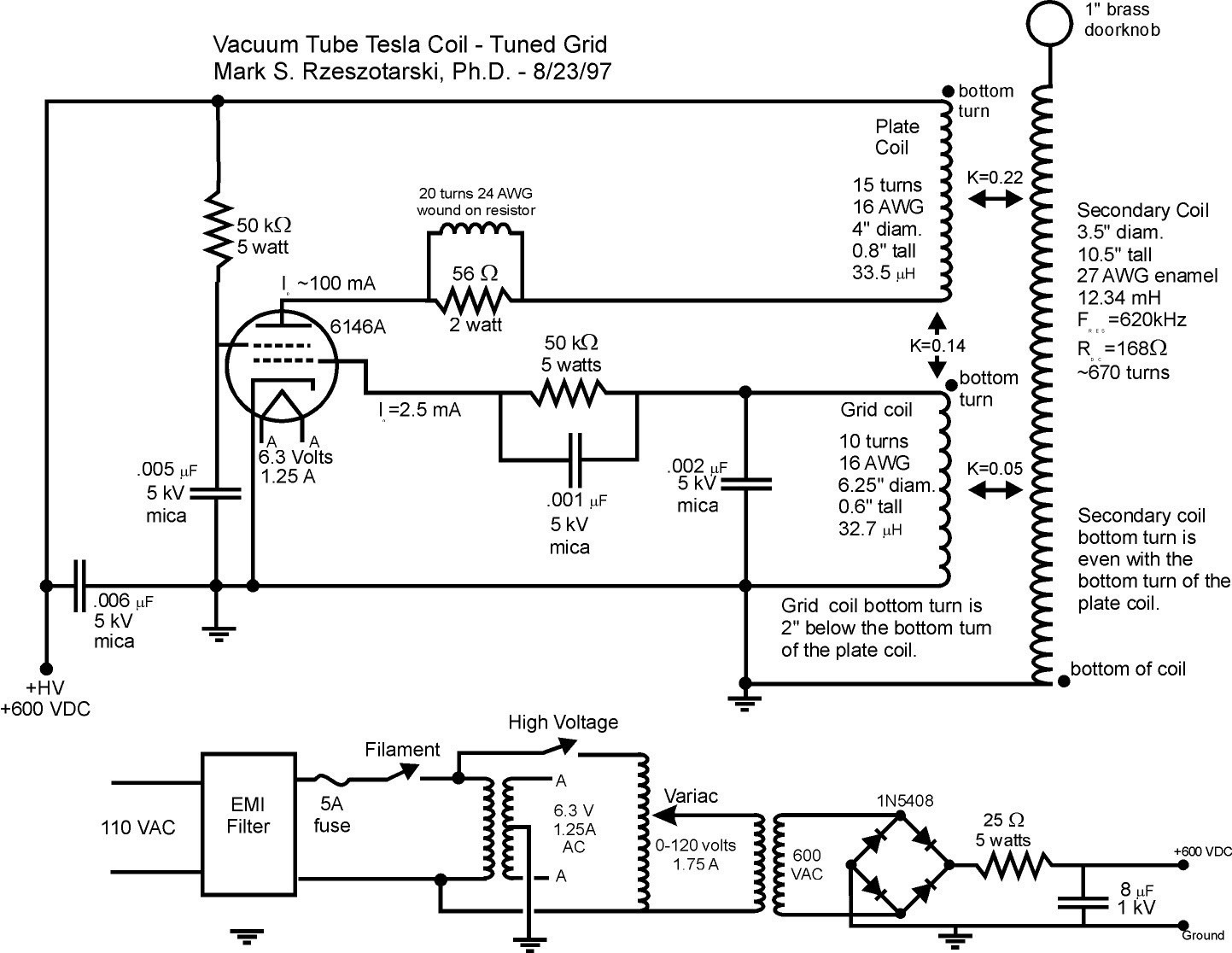
The vacuum tube Tesla coil operates by utilizing a 6146A beam power vacuum tube, which is capable of delivering a power output of approximately 35 watts. The design incorporates a grid circuit that functions as the tank circuit, consisting of an inductor and a capacitor tuned to resonate at the secondary coil's frequency. This configuration allows for effective energy transfer and generates RF pulses at a frequency of 620 kHz. The system operates in Class C mode, with a grid voltage of -68 volts, producing an average plate current of 100 mA.
The coupling coefficients are crucial in determining the interaction between the various components of the circuit. The plate circuit is tightly coupled to the secondary coil, which facilitates the delivery of energy in short RF pulses. The grid tank circuit is loosely coupled to the secondary, enhancing frequency stability during experimentation, while the grid coil maintains a moderate coupling to the plate coil to sustain oscillations.
Safety considerations are paramount when working with high-voltage systems. The design has been tested for continuous operation without overheating, indicating its suitability for extended use. The incorporation of neon bulbs for voltage distribution visualization provides a practical means to study the electric field around the coil, allowing for educational demonstrations while emphasizing the need for caution due to the potential for RF burns and electrocution. The overall design and operational characteristics of this vacuum tube Tesla coil present a unique opportunity for exploration and experimentation within a controlled environment.Vacuum tube tesla coils operate in a continuous wave mode of operation, continuously providing energy to the tesla coil secondary. As a result, the output is primarily determined by how much power the vacuum tube can process. The spark discharge and operation of these coils is quite different from disruptive coils. If a D. C. voltage is used to operate the coil, the spark breakout hisses, as opposed to the 60 cycle hum normally associated with an A. C. operated vacuum tube coil. The following text and images describe a small vacuum tube tesla coil which uses a single 6146A or similar beam power vacuum tube. Other television horizontal amplifier tubes can be readily substituted if desired. The approximate power output is 35 watts, and the unit is capable of generating a brush discharge of approximately one inch in length.
Normally, a small brass knob is attached to the top of the coil so that spark breakout is inhibited. In this case, considerable R. F. energy is generated, and luminous tubes (e. g. , neon, argon, xenon filled gas tubes) can be readily ionized and caused to glow while held in the hand several feet away from the coil. This provides an opportunity for considerable study in a relatively safe operating environment, compared to most tesla coil systems.
Note that although this coil operates at 620 kilohertz, it is quite capable of causing severe R. F. burns, and electrocution is also possible due to the high voltages used in its operation. The information provided here is for educational purposes only. If you are not experienced in the construction of high voltage apparatus, do not attempt this project! Please also read the safety FAQ on tesla coils before you attempt to construct these devices. The coil is of a slightly different design than the conventional tickler feedback coil system often published in the literature.
In this design, the grid circuit is the tank circuit, containing the inductor and capacitor which are tuned to the secondary resonant frequency. Most published systems use a tuning capacitor in the plate circuit. The plate circuit is tightly coupled to the secondary (K=0. 22) delivering the energy in the form of short intense R. F. pulses, operating well into class C with a grid voltage of -68 volts. It is a D. C. coil, so the pulses occur at a rate of 620, 000 times per second. The plate current averages 100 mA. The grid tank circuit is loosely coupled to the secondary (K=0. 05) and operates with an average grid current of 2. 5 mA. The grid coil is coupled to the plate coil more tightly (K=0. 14) so that oscillations can be sustained. By using loose coupling in the tank circuit, frequency stability is less affected when objects are brought near to the coil for experimentation.
The coil can be operated continuously, since it was designed to be within the maximum limits for the vacuum tube selected. It was recently powered up for demonstration purposes for several hours of continuous operation without overheating or malfunction.
A plastic rod containing a series of 20 or so small NE-2 neon bulbs insulated from each other can be held next to the coil to demonstrate the voltage rise pattern of the secondary. Since neons turn on at about 90 volts, the electric field distribution can be studied with this device near a small coil such as this.
The effect is best seen by varying the variac voltage on the high voltage supply. The voltage distribution follows the properties of a quarter wave helical resonator, demonstrating a voltage minimum at the base of the secondary coil and a voltage maximum at the top of the coil. After 15-30 minutes of operation, the temperature of the coil becomes slightly elevated, and the base is considerably warmer than the top of the coil, confirming that the current is a maximum at the base and a minimum at the top of the coil.
Additional information can be extracted from the original schematic (42 Kb) or the cleane 🔗 External reference
Related Circuits
This project is a fun and safe activity for individuals interested in magnetically launching projectiles. The operation involves placing a ferromagnetic projectile at one end of a coil and applying a power pulse. The key is to turn off...
This design is based on a publication by Milan Lulic in the German magazine elektroModell. Lulic's design utilizes surface mount technology (SMT), while this version employs standard off-the-shelf components, making it more accessible for hobbyists. For those interested in...
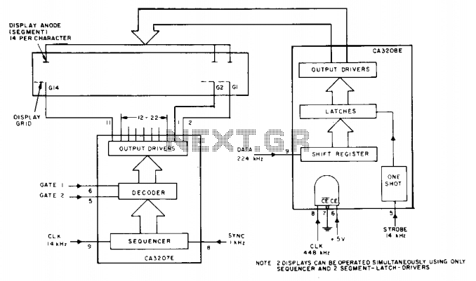
This circuit utilizes the CA3207 sequence driver and the CA3208 segment latch driver in conjunction to control display devices featuring up to 14 segments, accommodating a maximum of 14 characters. The CA3207 sequence driver functions by selecting the specific digit...
The PCD3360 is a CMOS integrated circuit designed to replace the electro-mechanical bell in telephone sets. It meets most postal requirements, featuring selectable output tone sequences and input ringer frequencies. The circuit provides output signals suitable for driving a...

A bridge circuit is utilized to generate a signal from the output of vacuum sensor IC1. IC2b introduces an approximate 0.2 V offset for IC4, the A/D converter. IC2b and IC2d function as voltage followers that drive the differential...
This webpage is designed to provide assistance and information for individuals interested in constructing a Tesla coil. It is recommended to utilize the additional resources available on this page. The electrical line voltage standard in the United States is...