
Digital Vacuum Gauge

The described circuit employs a bridge configuration to effectively convert the readings from a vacuum sensor, represented by IC1, into a usable electrical signal. The bridge circuit is adept at detecting small changes in the vacuum level, which is crucial for applications requiring precise measurements, such as in pressure sensing or environmental monitoring systems.
IC2b plays a critical role by introducing a small offset voltage of approximately 0.2 V. This offset is essential for calibrating the output signal to ensure that the A/D converter, IC4, accurately processes the data without losing sensitivity at lower vacuum levels. The role of IC2b, along with IC2d, as voltage followers is significant; they buffer the signal from the bridge circuit and ensure that the differential amplifier IC2a receives a stable and accurate representation of the input signal.
Differential amplifier IC2a enhances the difference between the two input signals, improving the signal-to-noise ratio and ensuring that the output is more robust against common-mode noise. This amplified output is then directed to IC4, the A/D converter, which converts the analog signal into a digital format suitable for further processing, display, or logging.
Finally, both IC4 and IC1 serve as display drivers, indicating the processed data to the user. The integration of these components within the circuit allows for a coherent and efficient system capable of providing accurate readings from the vacuum sensor, with the capability to display this information in a user-friendly manner. The overall design emphasizes precision and reliability, essential characteristics in electronic measurement systems. A bridge circuit is used to produce a signal from the output of vacuum sensor IC1. IC2b provides about a 0.2 V offset for IC4, the A/D converter. IC2b and d are voltage followers that drive differential amp IC2a. The output of this circuit is used to drive IC4 and IC1, the display drivers. 🔗 External reference
Related Circuits
This circuit was designed for digital cameras, which are known to have significant power consumption. For instance, the Minolta E223 camera requires approximately 800 mA. In practice, this demand can be met using a mains power supply or high-capacity...
The circuit operates using AC mains voltage and other high voltages that pose risks of injury or death. The 125 employs a basic heterodyne configuration, where the outputs of two similar radio-frequency Colpitts oscillators are fed into a mixer,...
This is an easy-to-build yet highly accurate digital voltmeter designed as a panel meter. It can be utilized in DC power supplies or any application requiring precise voltage readings. The circuit uses the CL7107 Analog to Digital Converter (ADC)...
The reason for this project was to facilitate a quick installation for a local friend 10 km away, enabling the start of real-life testing to identify and resolve bugs and problems before releasing it to other users. The software...
This circuit is designed for accurate centigrade temperature measurement. It features a transmitter section that converts the sensor's output voltage, which is proportional to the measured temperature, into a frequency signal. The output frequency bursts are transmitted through the...
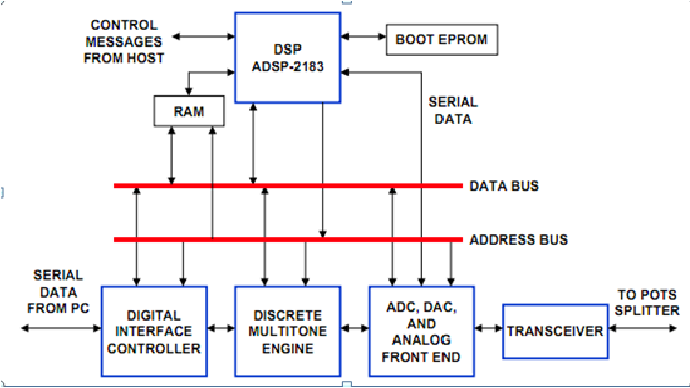
DSP Applications in ADSL (Asymmetric Digital Subscriber Line) can be explored further in Microsoft Office Word. The widespread popularity of the World Wide Web has led to unprecedented levels of Internet traffic. A recent study by the Wall Street...