
MiniDCC Project

The described circuit involves the integration of a PIC microcontroller (16F88) that functions as the central processing unit for controlling multiple DCC (Digital Command Control) equipped model train engines. The architecture allows for automatic control of up to four engines, facilitating their start and stop operations based on their respective positions on a circular track layout.
The communication between the PIC and the MiniDCC controller is established via a keypad interface. The keypad is constructed using a custom 4 x 4 matrix design, employing 16 SPST momentary switches. This design choice enables user interaction for selecting various functions and settings related to the operation of the DCC engines. The keypad connections are managed through two 4066 analog switches, which provide the necessary signal routing while conserving the limited I/O pins available on the 16F88 microcontroller.
To enhance the functionality of the control unit, an infrared (IR) remote control is incorporated for changing settings dynamically. The IR receiver, PNA4602M, is specifically selected for its ability to detect signals modulated at 38 kHz, which is standard for most consumer IR remote controls. This feature allows the user to interact with the control unit wirelessly, providing a convenient and flexible means of operation.
Programming of the 16F88 is conducted using PIC Basic Pro, a high-level programming language suited for microcontroller applications. The initial test code has been developed to verify the circuit's functionality and the interaction between the components, although it is noted that the current implementation does not yet include train position sensing capabilities. Future iterations of the project may incorporate position detection to further enhance the control system's automation and responsiveness.
Overall, this design represents a sophisticated approach to model train control, integrating both wired and wireless communication methods while utilizing a microcontroller to manage multiple engines efficiently.Develop a self contained unit that can automatically control up to four DCC equipped engines, starting and stopping them based on their position on a loop of track The control PIC interacts with the MiniDCC controller through the MiniDCC`s keypad. Six pins from the 16F88 will connect to the keypad through a pair of 4066 ICs. Because of a limited n umber of available pins on the 16F88 an infrared TV remote control is being used to change settings on the controller. The IR signal is received by the PNA4602M. It is made to react only to IR signals that are modulated at 38 KHz, the frequency used by a typical TV remote control unit.
The 16F88 controller is programmed using PIC Basic Pro. The test code for the controller is below. Note that it is not yet able to sense train position. It is being used primarily to test the circuit and its components. I chose to make up my own 4 x 4 keypad matrix from 16 discreet SPST momentary switches - the ones I have chosen are from Electronic Goldmine (part number G1412) 🔗 External reference
Related Circuits
This circuit utilizes a 555 timer configured to operate in astable mode. This setup generates a continuous output through Pin 3 in the form of a square wave. When the timer's output transitions to a high state, it triggers...
The microcontroller board is displayed (top left/green board) alongside the auxiliary board (bottom left/brown board) and two geared Hurst stepper motors. In this view, the programming jumper is located in the upper right area of the microcontroller board, while...
It is a wireless doorbell with a cost of about $10.00. This product encourages a shift in approach to building projects, utilizing such items to learn about their functions and modify them to meet specific needs. The doorbell incorporates...
Nowadays, every institution requires automation. As part of college automation, a project has been developed titled "Voice Interactive System for College Automation." This project enables users to quickly access student attendance and marks through a telephone line without the...

The input capacitor is used for low-frequency cut-off, with a standard value of 0.1 µF, resulting in a cut-off frequency of approximately 16 Hz. The input capacitor plays a critical role in electronic circuits, particularly in signal processing and audio...
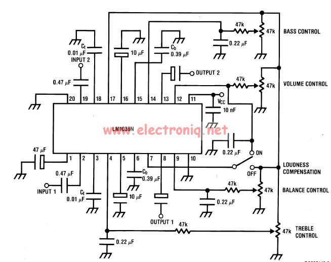
This volume controller equalizer electronic project is designed using the LM1036 DC tone volume controller, featuring a volume and balance circuit for stereo applications. The four control inputs of the LM1036 volume controller enable the control of bass, treble,...