
Police Lights associate crystal rectifier Project

The circuit design incorporates a 555 timer IC, which is a versatile component commonly used in various timing applications. In astable mode, the 555 timer continuously oscillates between high and low states, producing a square wave output. The frequency of this oscillation is determined by the resistor and capacitor values connected to the timer. Typically, two resistors (R1 and R2) and a capacitor (C1) are used to set the timing parameters. The output frequency can be calculated using the formula:
\[ f = \frac{1.44}{(R1 + 2R2) \cdot C1} \]
The output from Pin 3 of the 555 timer is fed into the clock input of the CD4017 decade counter. The CD4017 is a popular decade counter that counts from 0 to 10 and provides ten output pins (Q0 to Q9). Each time a clock pulse is received, the counter increments its count by one, activating the corresponding output pin. This means that the first output pin (Q0) will turn on the first LED, the second output pin (Q1) will turn on the second LED, and so forth, creating a visual indication of the counting process.
The LEDs connected to the outputs of the 4017 will turn on and off in sequence as the counter increments. A current-limiting resistor should be used in series with each LED to prevent excessive current from damaging the LEDs. The choice of resistor value depends on the supply voltage and the forward voltage drop of the LEDs, calculated using Ohm's law.
This circuit can serve various applications, such as visual indicators, light chasers, or educational demonstrations of counting and timing principles in electronics. The simplicity and effectiveness of the 555 timer and CD4017 combination make it a popular choice for hobbyists and professionals alike.This circuit uses a 555 timer that is setup to each runn in associate Astable operative mode. This generates a nonstop output via Pin three within the type of a sq. wave. once the timer`s output changes to a high state this triggers the a cycle the 4017 4017 decade counter telling it to output consecutive sequent output high. The outputs of the 40 17 ar connected to the LEDs turning them on and off. 🔗 External reference
Related Circuits
This digital dice electronic project utilizes a combination of a 555 timer, a 7490 decade counter, a 7483 4-bit binary adder, a 7447 BCD to 7-segment decoder, and a 7-segment display to show the digit. The digital dice project is...
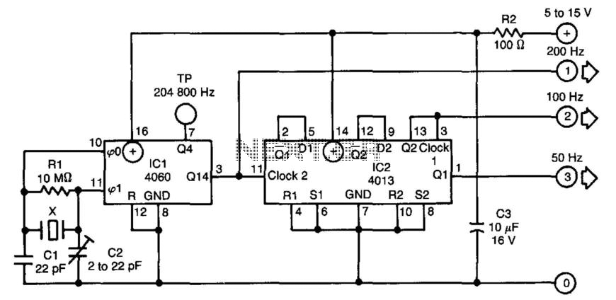
The time base circuit described above generates 50, 100, or 200 Hz signals using an inexpensive crystal oscillator cut for 3.2768 MHz, which is commonly utilized in microprocessor applications. The circuit operates on a power supply range of 5...
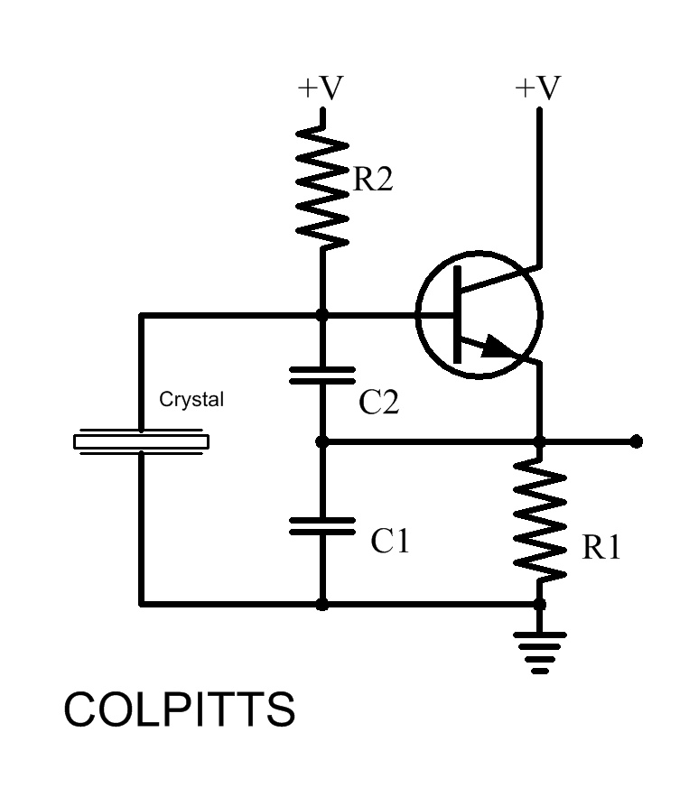
Inquiries about selecting the L, C, and R values to achieve a desired frequency are common. It is essential to understand the relationship between these components and the frequency they produce. The desired frequency can be calculated using the...
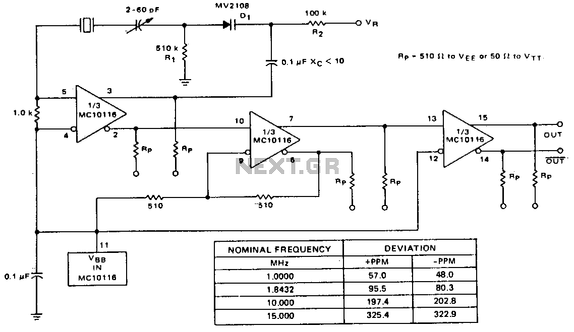
A voltage-variable capacitance tuning diode is connected in series with the crystal feedback path. Adjusting the voltage on the variable resistor (VR) changes the capacitance of the tuning diode, which in turn tunes the oscillator. The 510 kΩ resistor...
This simple circuit drives six LEDs in a "Knightrider scanner mode." Power consumption primarily depends on the type of LEDs used, especially if a 7555 (555 CMOS version) is utilized. The circuit operates by sequentially illuminating the LEDs to create...
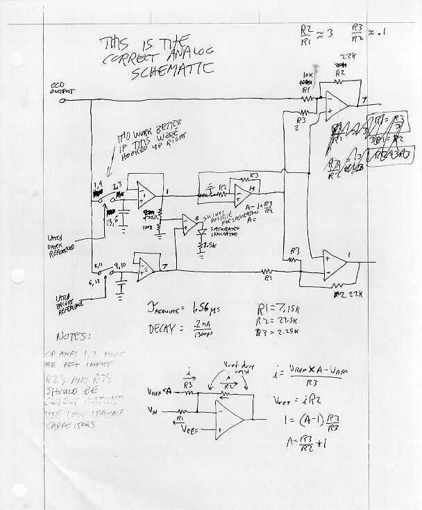
The CCD Array Reader project began with a free sample of the Texas Instruments TC102-1 CCD Linear Image Sensor and its rather terse data sheet. The TC102-1 provides virtually no support circuitry, only the raw CCD (with a few...