
Simple Peak Detector Circuit schematic with explanation

The circuit design effectively employs the 1458 dual operational amplifier to achieve peak voltage detection from an input waveform. The first op-amp, configured as a voltage follower, ensures that the output voltage closely follows the input voltage, allowing for efficient charging of capacitor C1. This configuration is crucial for accurately capturing the peak voltage of the input signal, as the voltage across C1 will reflect this maximum value.
The diode D1 plays a vital role in preventing the discharge of C1 back into the op-amp, ensuring that the capacitor retains its charge after reaching the peak voltage. This characteristic is particularly important in applications where the peak voltage must be maintained for further processing or analysis.
The second op-amp serves as a buffer, isolating the capacitor from the subsequent circuitry. This buffering action minimizes any load effects that could result in voltage drops, thereby preserving the integrity of the voltage stored in C1. This feature is essential for applications requiring precise voltage levels.
The reset switch allows for manual intervention to discharge the capacitor. This functionality is important for applications that need to detect new peak voltages at irregular intervals. By discharging C1, the circuit can be reset and prepared to capture the next peak voltage accurately.
Overall, this circuit design demonstrates an efficient method for peak voltage detection using a dual op-amp configuration, ensuring accurate voltage tracking and minimal signal degradation. The combination of a voltage follower, buffer, and reset mechanism provides a robust solution for various electronic applications requiring peak voltage monitoring.The circuit uses a dual operational amplifier IC, the 1458, which is a single IC package that houses two individual op-amps. In this circuit, the first op-amp is used as a voltage follower whose output is used to charge the capacitor C1 through D1.
As such, the voltage to which capacitor C1 charges up to is the maximum voltage that the input wavef orm reached, i. e. , its peak voltage. The second op-amp of the 1458 is used as a buffer that outputs the capacitor voltage with negligible loss in the capacitor charge. The reset switch is used to discharge the capacitor if a new input peak voltage needs to be detected.
🔗 External reference
Related Circuits
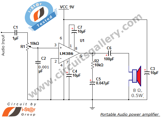
The i-St@r presents a simple mini audio amplifier circuit schematic utilizing the LM386 low voltage audio power amplifier IC. This circuit is designed to power medium-sized speakers from a music player that typically drives only earphones (LM386 headphone). The...
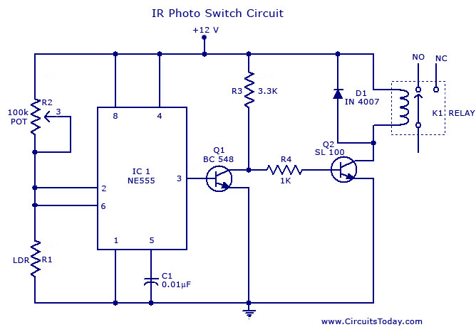
A simple photo switch circuit using an NE 555 IC with a diagram and schematic. This photo switch activates a relay when light intensity crosses a specified limit. It is a light sensor circuit suitable for home and industrial...
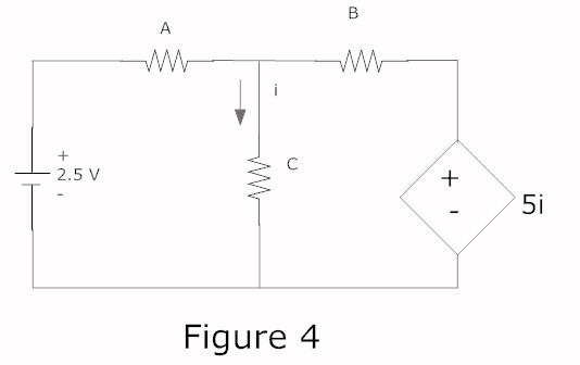
In a complete circuit, there are two types of elements: active and passive elements. Active elements generate energy, while passive elements dissipate energy. Examples of passive elements include resistors and capacitors. In electronic circuits, active and passive components serve distinct...
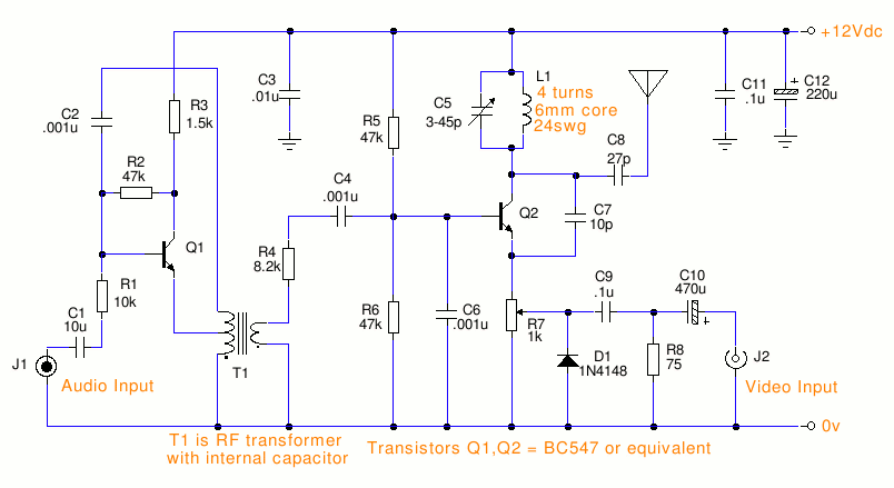
This is a small TV transmitter circuit that transmits in VHF, utilizing negative sound modulation and PAL video modulation. It is suitable for countries that use the B and G system. T1 refers to a type of transformer. The...

The 10K resistor is necessary if the receiver is to mute (squelch) under no-signal conditions. An additional 100K resistor can be added in series with this resistor to create an adjustable squelch. This circuit is designed to drive a...
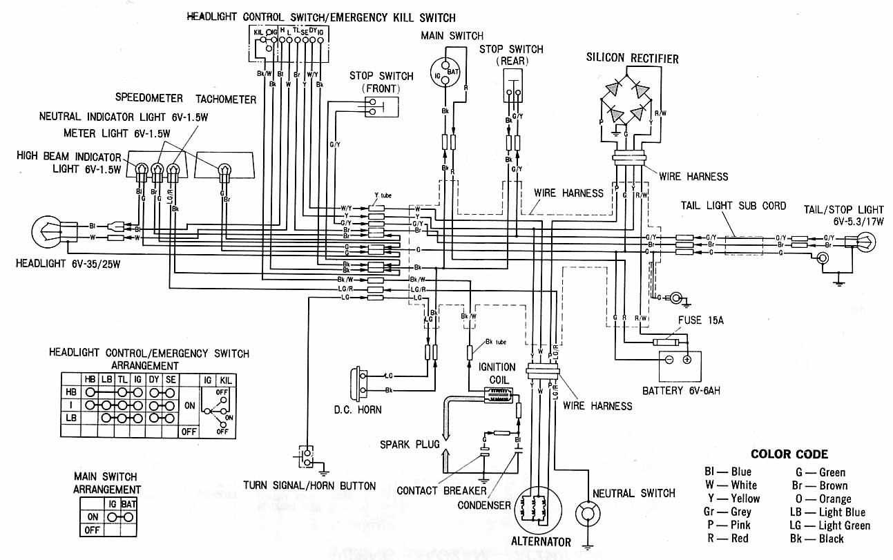
Honda XL100 electrical schematic. Features: shows the connection between Honda parts. Component: Silicon rectifier unit, wiring harness, tail light sub cable, tail/stop light, high beam indicator, m light, speedometer, tachometer, fuse headlight control switch, emergency kill switch, switch, stop...