
IR Remote Control Modulation Detector
The schematic of this circuit includes the following components: an IR photodiode (TIL100) connected through a 22 kΩ resistor for reverse biasing, a coupling capacitor (10 nF) to block DC components while allowing AC signals to pass, and two BC549C transistors configured in a cascading amplifier arrangement. The first transistor amplifies the signal received from the photodiode, while the second transistor operates in Class D mode to further process the signal. The output of the second transistor can be connected to a CMOS 4050 buffer for additional signal integrity. The design ensures that the circuit can effectively capture and display the modulated carrier wave from various infrared remote controls, facilitating the measurement of modulation frequencies and analysis of control signal characteristics. Proper layout and grounding practices should be employed to minimize interference, particularly from nearby fluorescent lighting, and to optimize the performance of the photodiode and amplifying stages.A circuit to extract and measure the modulated carrier of an Infra Red remote control. Note that the circuit does not physically separate control pulses from modulation, but amplifies the completereceived signal allowing the waveform to be displayed ideally on an oscilloscope or a frequency counter. Modulation frequencies between 1kHz and several MHz may be measured. All remote controls employing Infra Red technology use digital control signals that are modulated with a higher frequency carrier wave. The carrier wave, which is invisible to the human eye is commonly modulated between 36 and 38KHz. However, some equipment i. e. Satellite decoders may use even higher modulating frequencies. The digital control signals are relatively slow compared to the carrier frequency, typically 100 to 200 bps (bits per second).
The control pulses are sent in serial format and turn the carrier on and off. Fortunately, the control pulses of a typical remote control are long, compared to the faster modulated IR carrier wave. This very fact allows at least a few complete waveforms to be captured and measured, either on an oscilloscope or with a digital counter.
As the carrier is continually being modulated, the waveform will need to be displayed with a digital counter has a variable trigger or with an oscilloscopes manual trigger control. Light interference from nearby fluorescent light sources may also interfere with the signal, so, for this reason, I recommend to place the remote control within a few inches of the photodiode.
The detector is an IR photodiode, type TIL100. This is reverse biased via the 22k resistor and produces small changes in current when subjected to light in the IR spectrum. Ambient or steady light will produce a constant current through the photo diode, a remote control produces an alternating waveform.
The input signal is capacitively coupled to the first BC549C amplifier stage via a 10n capacitor. The capacitor will stop ambient light from passing, but not changes in light intensity. A signal of a few microamps can be passed from the photo diode into the amplifier. The high current gain of a BC549C and a medium load resistor will produce a voltage waveform that may be suitably displayed on an oscilloscope at this point. The magnitude will vary with the proximity from remote control to photo diode and also with type of remote control, hence an accurate reading is not possible.
For anyone with an oscilloscope set the volts/division control to maximum and work backwards to minimum sensitivity. The lower sensitivity of a frequency counter requires the signal to be processed further. To remove the previous amplifiers DC bias voltage, but allow only a strong modulated carrier wave to pass the last stage operates in Class D mode.
In Class D amplifiers, there are no bias components, the signal from the previous stage is used as the bias source. Therefore there will be no signal output at the collector of the rightmost BC549C under quiescent conditions, but only with a strong IR signal ( in close proximity to the photo diode).
The output transistor will be on when a positive peak arrives, and off for a negative peak. This crude method has also turned the original sinusoidal waveform into a digital one, there will be some phase shift from input to output, but the period of the waveform can still be measured. The signal can be buffered even further, if needed, the black triangle represents one gate of a CMOS 4050 buffer.
As control pulses are combined with the carrier, a frequency meter or counter is best set to measure the period of the wave, rather than the frequency. As frequency is the reciprocal of periodic time, divide 1 by the reading on the meter or counter. My own Maplin frequency counter, is shown below, displaying the result from an Aiwa Video remote control.
As can be seen (use a right click and choose your internet browsers view image) the periodic wavefor 🔗 External reference
Related Circuits
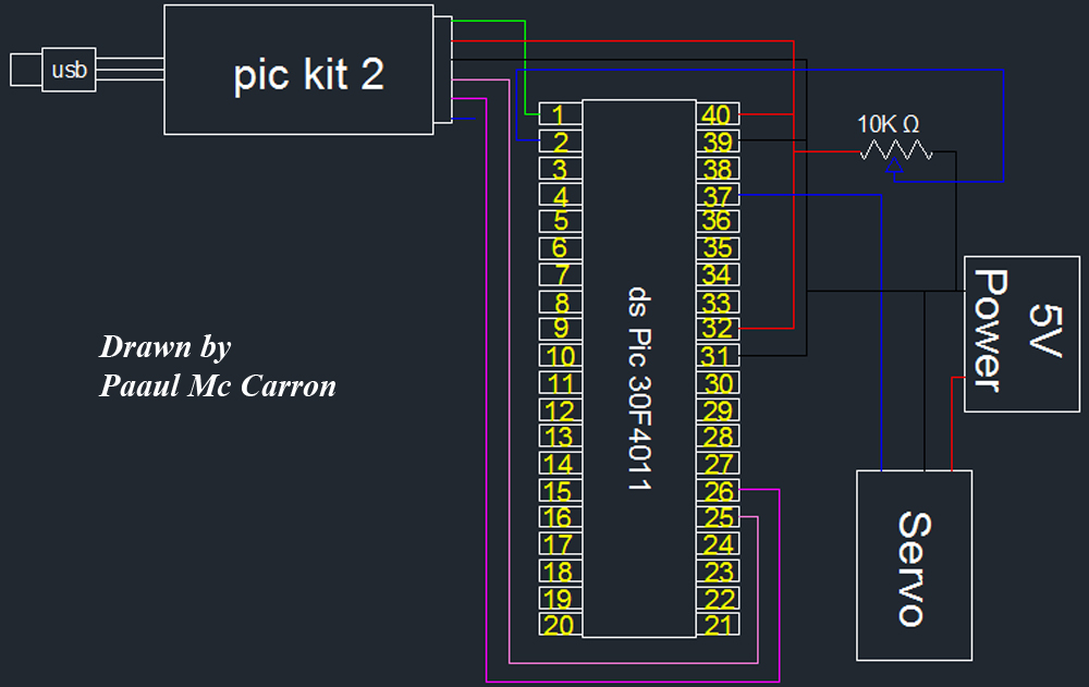
One of the motors utilized in the module is a servo motor. A servo motor is a compact motor that allows for precise positioning at various angles. It is equipped with internal circuitry that automatically maintains the specified angle....
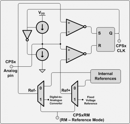
There are numerous applications for this hardware, including touch pads, proximity sensors, capacitive sensor readouts, high-precision capacitance measurements, ultra-small capacitance change detection, soil moisture sensing, and skin moisture measurement, among others. However, after searching for examples, it was surprising...
P1 47K logarithmic potentiometer; P2, P3 47K linear potentiometers; R1, R3, R5 4.7K 1/4W resistors; R2 22K 1/4W resistor; R4 1M 1/4W resistor; R6 1.8K 1/4W resistor; R7 560Ω 1/4W resistor; C1, C4, C5, C7 10 µF 63V electrolytic...
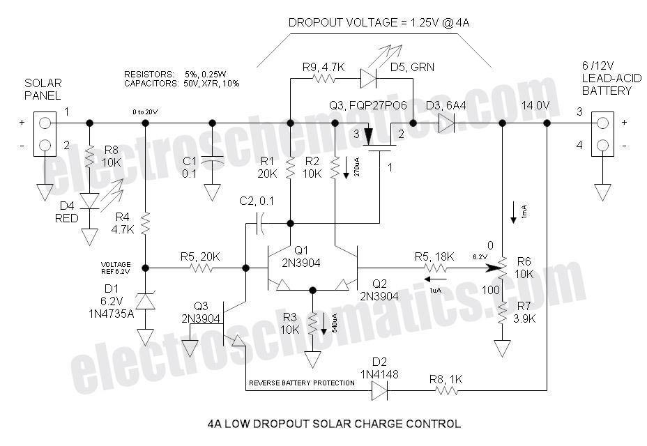
This Low Dropout Voltage (LDO) solar charge controller employs a differential amplifier and a series P-channel MOSFET linear regulator, which work exceptionally well together. The output voltage is adjustable and primarily designed for charging 12V lead-acid batteries. The input...
Based on the classic Baxendall tone control circuit, this provides a maximum cut and boost of around 10dB at 10K and 50Hz. The first BC109C transistor (left hand side) is acting as a buffer. It provides the circuit with...
This is a general-purpose remote control project utilizing programmable PIC microcontrollers. Schematics are provided for using infrared (IR) or radio frequency (RF) media. If microcontroller programming is unfamiliar, fixed encoder and decoder integrated circuits can be employed instead. Well-known...
Warning: include(partials/cookie-banner.php): Failed to open stream: Permission denied in /var/www/html/nextgr/view-circuit.php on line 713
Warning: include(): Failed opening 'partials/cookie-banner.php' for inclusion (include_path='.:/usr/share/php') in /var/www/html/nextgr/view-circuit.php on line 713