
Mitsubishi: I am putting a hydraulic thumb on my excavator heads
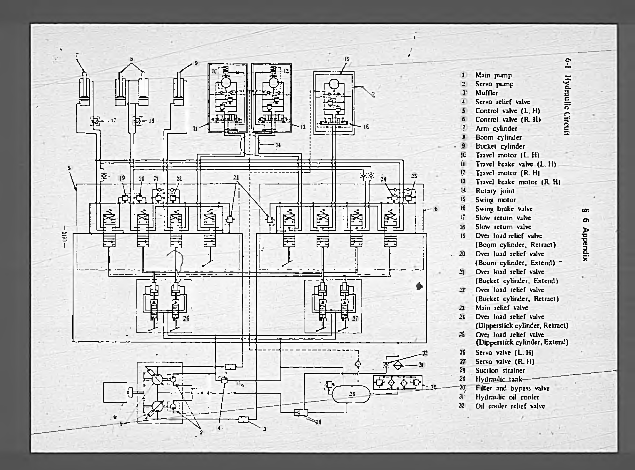
The Mitsubishi MS280 excavator utilizes a hydraulic system that incorporates multiple components for effective operation. The primary hydraulic pumps are complemented by servo or pilot valves that facilitate precise control of hydraulic flow to various actuators. The mechanical linkage connecting the operator's levers to the pilot valves serves as an interface for user input, translating manual movements into hydraulic commands.
In the proposed modification to integrate an electronic proportional control valve, it is essential to ensure compatibility with the existing hydraulic architecture. The electronic valve will allow for more nuanced control over the hydraulic flow, enhancing the responsiveness and efficiency of the excavator's operations. The installation would require careful consideration of the hydraulic circuit, ensuring that the electronic valve is correctly plumbed to interact with the pilot valves and main control valves.
The gear pumps associated with the main pumps are critical for maintaining hydraulic pressure in the system. The observation that moving the spool in the valve excited the pump indicates that the internal porting may play a significant role in the hydraulic circuit's functionality. Understanding this interaction is vital for troubleshooting and optimizing the system.
The hydraulic circuit's design, which includes pressure lines and return lines, must be analyzed to ensure that the proposed electronic valve does not disrupt the existing flow dynamics. The absence of a return line to the pump in the current configuration suggests that the system relies on load sensing to manage hydraulic pressure. This load-sensing mechanism adjusts the pump's output based on the demands of the hydraulic system, a feature that should be preserved while integrating the new control valve.
The recommendation for an open center valve highlights the necessity for the valve to handle the full flow capacity of the system, estimated at 57 gallons per minute. Additionally, the adjustable relief settings are crucial for protecting the hydraulic components from excessive pressure, ensuring operational integrity.
In conclusion, the integration of an electronic proportional control valve into the Mitsubishi MS280 excavator's hydraulic system presents an opportunity for improved control and efficiency. However, careful attention must be paid to the existing hydraulic architecture, ensuring that all components function harmoniously to maintain the excavator's performance and reliability.The excavator is Mitsubishi MS280. The problem is they are not sure how to excite the pump, I want to put an electronic proportional control valve in the old girl. If your familiar with this era of Mitsubishi`s could you let me know and I will give you as much detail as I can.
I will try to explain what I have and what I believe is happening. The levers are mechanical linkage to what I think is pilot valves under the cabin. The other side of these valves is also mechanical linkage to the control valves. The reason I think they are pilot valves is because there is a separate gear pump on each of the main pumps. These gear pumps are plumbed to these valves and to tank. So what we did was disconnect the mechanical linkage between the pilot valve and the main valve and installed a gauge on the main pump which we expected to see pressure when we activate the corresponding lever to the pilot valve, but the pump did not excite and we had no pressure.
So whilst the linkage was disconnected from the control valve we moved the spool in the valve and that excited the pump, so maybe there is some internal porting in the control valves. If so why would there be what look like pilot valves, I can`t understand there purpose with this test we did.
I did try to add a diagram of the hydraulic circuit from the doggie manual that I have, they call the pilot valves, servo valves, but I was unable to get a clear picture to attach to this message, I tried for an hour but the resolution is so large it was unviewable, I don`t know why as on my computer it read fine, I even put it on PDF and it came up well, but couldn`t attach it to here. If you have any other way I could send it to you please let me no. Yeah, ok. I haven`t progressed any further here with anybody. Like I said though I do have the hydraulic circuit diagram from the manual on a PDF file. I can`t quit follow what`s going on with the valves to excite the pump. It shows the pressure line to the valves and then after the valves back to the pump, where as my machine doesn`t have a line back to the pump.
I could email you a copy if you give me your address. I would like to see that file. You can upload it here by creating a link. Use the chain link icon in the tool bar, it is next to the smiley face. Just type a word, highlight it and then click the link icon. Browse to the file on your computer and upload the file. I think I have found the right manual now. The schematics you sent me is for a MS280-2. This drawing shows only one servo pump. You stated your pump has two servo pumps attached to the end of each main pump. The only difference I can tell is the MS280-2 has what they call today "negative flow" lines returning to the main pump control heads. These lines only insure the pump stops flow when all the valves are in neutral. If a valve is not in neutral, the line is not receiving flow. Hence the "negative flow" designation. The MS280 does not use the negative flow. It it sensing load through the pump port. As the flow is restricted when a lever is moved, the pressure rises at the pump. The pump control head will adjust the swash plates to build pressure as needed. I feel you will need an open center valve plumbed in-line from the return line of one of the main control valves.
When the valve is operated, the restriction will excite the pump and build pressure for the valve. This valve must be large enough to allow full pump flow to pass through. Max flow appears to be 57 gallons per minute. It should also have adjustable circuit reliefs set 2500 to 2900 psi. This will give strength to hold but, not damage the thumb. The servo valves are only a "power assist" feature. They do not control the pump in any way other than move the spools to the main control valve. Pressure in this circuit is less than 500 psi. The schematic you sent makes more sense as you are right I have 2 servo pumps and no "negative flow" lines. Although the 🔗 External reference
Related Circuits
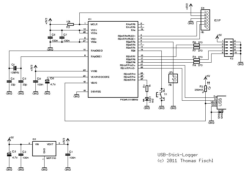
The default setting for the UART is 9600 baud, with 1 start bit, 1 stop bit, and no parity. This parameter can be configured by placing the file "CONFIG.TXT" onto the USB thumb drive. Currently, only the baud rate...
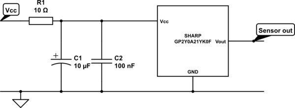
A project involves two distance sensors that signal an Arduino to operate a servo motor when an object comes within range. The system functions correctly; however, the sensors output a consistently high voltage, necessitating a high cutoff voltage in...
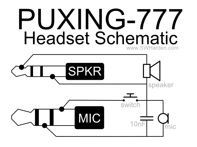
A speaker, microphone, and transmit button circuit designed for the Puxing 777 radio, which is likely compatible with all Puxing radios. The circuit was reverse-engineered from an earphone/microphone headset that originally accompanied the radio to understand its functionality. The...
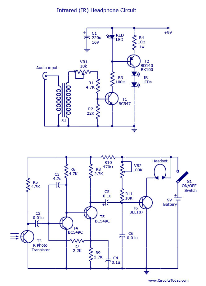
This document outlines a simple infrared (IR) headphone circuit designed for listening to television or radio without disturbing others. The IR headset is a preferable option for beginners compared to FM headsets due to its desirable sound quality that...
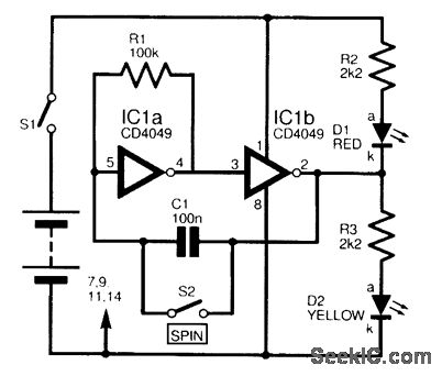
This circuit is designed to electronically simulate the tossing of a coin using a 4049 hex inverter integrated circuit (IC). It employs two of these ICs, specifically IC1a and IC1b, which are configured as an astable oscillator. This configuration...
This circuit consists of a single transistor functioning as an amplifier, providing significant amplification for weak and unipolar signals, which can then be fed into a more powerful amplifier. The described circuit utilizes a single transistor in a common-emitter...