
Puxing 777 Radio Headset Schematic
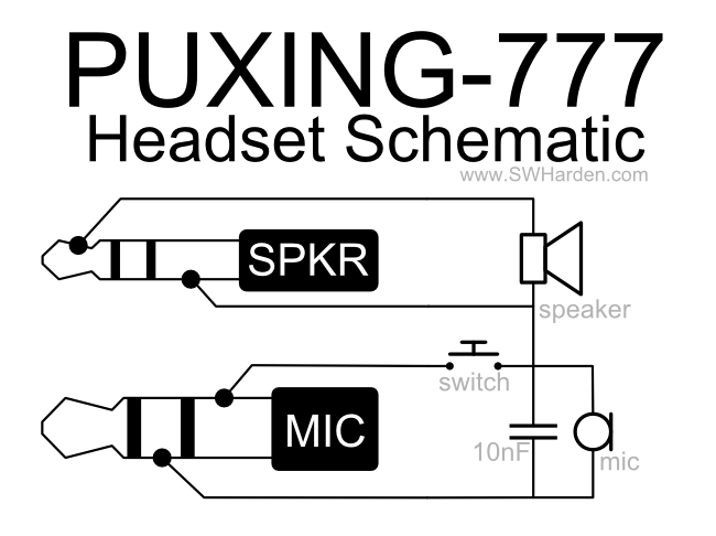
The circuit comprises several key components that work together to facilitate audio input and output, as well as transmission capabilities. The electret microphone is connected to a pre-amplifier circuit, which boosts the weak audio signal generated by the microphone before it is sent to the radio for transmission. This ensures that the audio quality is maintained and that the transmitted signal is clear. The 8-ohm loudspeaker is wired to the audio output of the radio, allowing the user to hear incoming communications.
The push-to-talk switch is a crucial component that allows the user to control when the radio is in transmit mode. When pressed, this switch connects the microphone to the radio's transmission circuit, enabling the user to communicate. The capacitor (10nF) serves a filtering purpose, smoothing out any voltage fluctuations that may occur during operation, which helps to prevent distortion in the audio signal.
The design is compact and suitable for desktop use, making it convenient for users who prefer to have a more stationary setup rather than relying on handheld operation. By positioning the radio on a charger while using the custom circuit, the user can ensure that the device remains powered and ready for use without the hassle of frequent battery changes.
The overall integration of these components aims to create a reliable and efficient communication system that enhances the functionality of the Puxing 777 radio. With further refinements and potential improvements, such as better audio processing or additional features, this circuit can serve as a foundation for creating a versatile desktop transceiver setup.A speaker/microphone/transmit button circuit for the puxing 777 which probably works for all puxing radios. I decided to reverse-engineering an earphone/microphone headset that came with the radio to determine how it worked.
I can`t claim that I`m an expert in electronics theory, but I can say that I faithfully rebuilt the circuitry within the factory-shipped headset and it worked. The result allows me to leave my handheld radio in its charger while casually listening/transmitting with a button that I made instead of having to reach around and awkwardly squeeze the transmit button on the side of the radio. Once again, I built this circuit and it was successful for me, but there may still be a better way to do it.
The microphone is a 20-cent electret microphone with no special modifications. The speaker I used is a standard 8ohm loudspeaker with no special modifications. The switch is a keyboard-style (push-to-talk) switch, and the capacitor I used is good for 10nF. If you have any ideas for improvements, let me know! I`ll post some photos once I have my completed little base station set up. My ultimate goal is to turn an el-cheapo handheld VHF radio into a decent desktop transceiver by combining it with a nice antenna (located on a balcony at 30ft) and a convenient, easy-to-use switches/buttons/microphone/speaker/etc on a desktop panel. Scott Harden has had a lifelong passion for computer programming and electrical engineering, and recently has become interested in its relationship with biomolecular sciences.
He has run a personal website since he was 15, which has changed names from HardenTechnologies. com, to KnightHacker. com, to ScottIsHot. com, to its current SWHarden. com. Scott has been in college for 10 years, with 3 more years to go. He has an AA in Biology (Valencia College), BS in Cell Biology (Union University), MS in Molecular Biology and Microbiology (University of Central Florida), and is currently in a combined DMD (doctor of dental medicine) / PhD (neuroscience) program through the collaboration of the College of Dentistry and College of Medicine (Interdisciplinary Program in Biomedical Science, IDP) at the University of Florida in Gainesville, Florida. In his spare time Scott builds small electrical devices (with an emphasis on radio frequency) and enjoys writing cross-platform open-source software.
🔗 External reference
Related Circuits
This circuit diagram represents a radio-controlled system, commonly used in toy car applications for children. The circuit consists of two main parts: the transmitter and the receiver. The transmitter generates radio signals using an oscillator circuit formed by transistor...
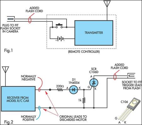
A radio-controlled electronic flash is an essential tool for any photographer's kit, frequently utilized by professionals. For instance, a wedding photographer may position one behind the bride to illuminate her gown and veil without visible wires in the shot....
Instead of using a 555 timer integrated circuit, this design employs two transistors configured back-to-back to function as a multivibrator. This arrangement modulates the direct current sufficiently to traverse the magnetic field of a transformer. It represents one of...
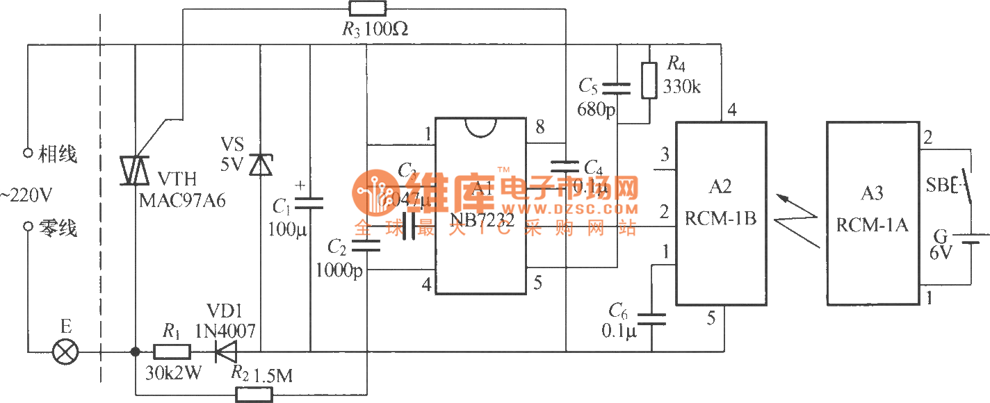
The diagram above illustrates a radio remote control dimmer circuit. This circuit utilizes a micro radio transmit/receive module in conjunction with a light modulation ASIC, resulting in a compact and easily producible design. It operates reliably and features a...
The LED arrangement in the LM339 circuit consists of two rows of three LEDs, with each LED connected in parallel. The two rows are connected in parallel but with reversed polarity. The sensor array is composed of three west-facing...
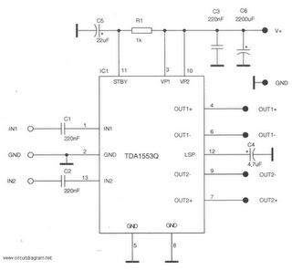
This is a 22-watt car stereo audio amplifier. The circuit is based on a single IC TDA1553 with a few peripheral components. This IC is designed for car audio applications. The TDA1553CQ integrates two 22-watt amplifiers with differential input...