
Model rocket launch controller
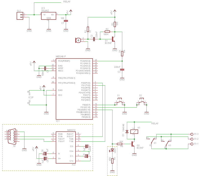
The circuit utilizes eight light-emitting diodes (LEDs) arranged to indicate the active pad selection in a user interface. These LEDs are connected to a decade counter, typically a CD4017 or similar, which serves to sequentially activate each LED in response to clock pulses. The operation is such that only one LED is illuminated at any given time, minimizing the current draw from the power source and ensuring efficient battery usage.
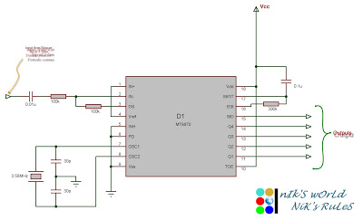
The clock signal necessary for the decade counter is produced by a 555 timer configured in astable mode. This configuration allows the timer to generate a continuous square wave output, which serves as the clock pulse for the counter. The frequency of the clock can be adjusted by varying the resistor and capacitor values in the 555 timer circuit, allowing for control over the speed at which the LEDs are cycled.
The control interface for this circuit includes six input lines that connect to a main controller. These lines are responsible for receiving signals that dictate which pad is selected. Depending on the logic levels present on these lines, the decade counter will be triggered to advance its count, thus lighting the corresponding LED. The simplicity of the circuit design facilitates easy integration into larger systems while maintaining clarity in operation.
Overall, this circuit exemplifies a straightforward yet effective method for visual pad selection indication using discrete components, ensuring low power consumption and ease of implementation.Eight LED`s are used to indicate the pad currently selected. These LED`s are connected to a decade counter, which sequences the LED`s when it receives a clock pulse.Only one LED can be lit at a time from the decade counter, so although this circuit contains many LED`s only a small drain us placed on the battery. The clock pulse for the decade counter is generated by a 555 timer. The circuit diagarm for the pad unit is very simple. Six input lines receive the signals from the main controller. I don`t think I need to explain this part of the circuit in detail, although I will mention a few things. Firstly make sure that the re 🔗 External reference
Related Circuits
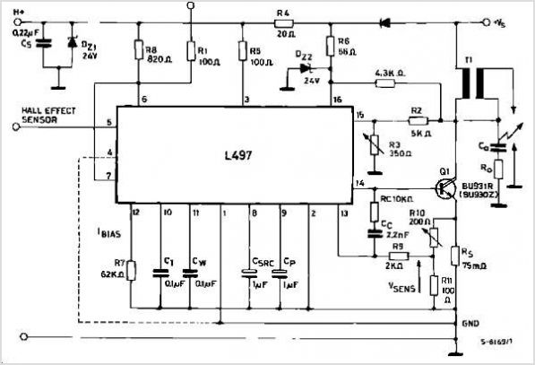
The LA1061M is an antenna switching controller designed for mobile radio equipment. It utilizes several inputs from the receiver circuitry to choose between the main antenna and a sub-antenna based on signal strength and quality. Weak and strong signals...
Connect the serial cable to the serial port. If using a USB to TTL, RS232, or serial converter, plug it into the USB port. Next, short the Tx pin to the Rx pin or the TxD pin to the...
This circuit automatically activates and deactivates a motorcycle's headlight, functioning independently of both the light and ignition switches, as long as the battery is fully charged. The initial stage employs a 220-ohm resistor and ZD1 to keep transistor Q1...
The Clock Controller was designed as an exemplary application of the C programming language to manage timer0 interrupts, control a 7-segment LED display, and perform keypad scanning. It offers a 1-bit sink current output suitable for driving devices such...
For those who prefer convenience, it is possible to turn the bedroom light on or off without leaving the bed simply by clapping hands. This concept inspired the design of a clap-activated light control system. Various clap switch projects...
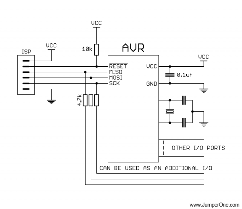
This schematic illustrates the placement of a decoupling capacitor on the right side, which should be positioned as close as possible to the power pins of the microcontroller. It includes a crystal oscillator, which is optional; an internal RC...
Warning: include(partials/cookie-banner.php): Failed to open stream: Permission denied in /var/www/html/nextgr/view-circuit.php on line 713
Warning: include(): Failed opening 'partials/cookie-banner.php' for inclusion (include_path='.:/usr/share/php') in /var/www/html/nextgr/view-circuit.php on line 713