
using microcontrollers
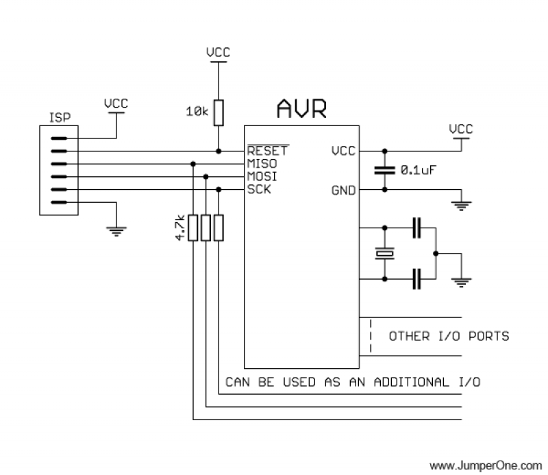
The schematic serves as a guide for designing a microcontroller-based circuit, emphasizing the importance of proper component placement to ensure reliable operation. The decoupling capacitor's proximity to the microcontroller's power pins is critical for filtering noise and stabilizing the power supply, which enhances the performance and reliability of the device. The optional crystal oscillator provides a precise clock signal, which can be essential for timing-critical applications, while the flexibility to use an internal RC oscillator or external clock signal allows for customization based on the specific needs of the project.
The 10k pull-up resistor on the RESET pin is a standard practice in microcontroller design, ensuring that the pin is held high during normal operation and can be driven low for programming. The inclusion of 4.7k resistors on the MISO, MOSI, and SCK pins allows for interfacing with other devices, highlighting the circuit's versatility. The choice of connectors, particularly the single row connector, facilitates easier access for programming and debugging, although users must be cautious of the non-standard pinout.
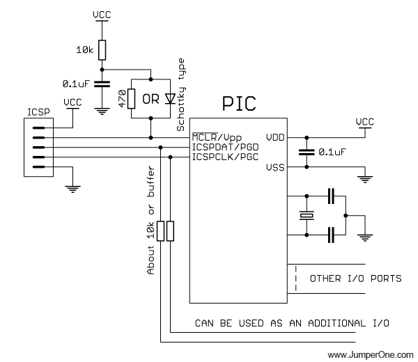
For programming PIC microcontrollers, the design incorporates safety measures such as the Schottky diode or resistor to manage the higher voltage applied to the MCLR pin. This consideration is crucial to prevent damage to the microcontroller during the programming process. The option to connect a 10k resistor directly to the MCLR pin simplifies the circuit in certain applications, providing additional flexibility.
The mention of PICKIT programmers underscores the relevance of external programming tools in the development process, offering a cost-effective solution for programming and debugging microcontrollers. The UART functionality expands the utility of these programmers, enabling communication with various devices, thus enhancing the overall capability of the microcontroller system.In this self-explanatory schematic you can see decoupling capacitor on the right, which must be as close to microcontroller`s power pins as possible; crystal oscillator, which is optional, because you can use internal RC oscillator or external clock signal, depends on your needs; 10k pull-up resistor for RESET pin, to allow external programmer to drive this pin low when
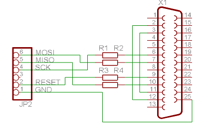
uploading firmware; ISP connector. And if you want to use MISO, MOSI and SCK pins for purposes other than firmware upoload, you can connect 4. 7k resistors between those pins and peripherals that you want to connect there. Two connectors on the left are from the most popular AVR programmer made by Atmel AVRISP mkII. And on the right is the pinout that I`m using in my projects, because it is much easier to work with single row connector than with double row ones.
But be aware it`s not a standard connector pinout. Since in PIC microcontrollers 12-13V applied to MCLR pin for programming you need to put schottky diode or 470 ohms resistor between RC circuit and MCLR pin. In some cases you can omit capacitor and diode and connect 10k resistor straight to MCLR pin. You can read more about this here: System Supervisors in ICSP Architecture and PICKIT 2 programmer manual.
PICKIT III and PICKIT II programmers are made by Microchip, they`re very cheap and have some additional functionality, like UART tool, which allows you to talk to the microcontroller or any other device using UART serial protocol.
Related Circuits
The Atmega 128 is similar to other AVR microcontrollers. It is in-system programmable (ISP). An earlier article discussed the AVR ISP programmer, which utilizes a 74HC244 buffer for safety when programming the AVR. However, if a programmer for the...
The ISD1000A is a Direct Analog Storage device which allows you to store 20 seconds worth of voice data on an IC chip which can be played back anytime. The data stored will stay in memory even if the...
This circuit is a melody generator circuit diagram controlled by the UM66 IC. The UM66 is a CMOS IC designed for applications such as call bells, telephones, and toys. It features a built-in ROM programmed to play music and...

How can a television modulator be small and simple? First, it utilizes integrated circuits, and second, a TV modulator is essentially an amplitude modulator. Television modulators are essential components in the transmission of television signals, converting audio and video signals...
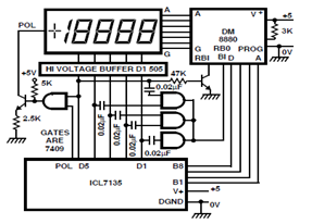
A circuit diagram for driving a plasma-type display using the ICL7135 is presented in the schematic. This application highlights the versatility of this integrated Analog to Digital Converter device. The ICL7135 is a high-precision, low-power, integrating Analog to Digital Converter...
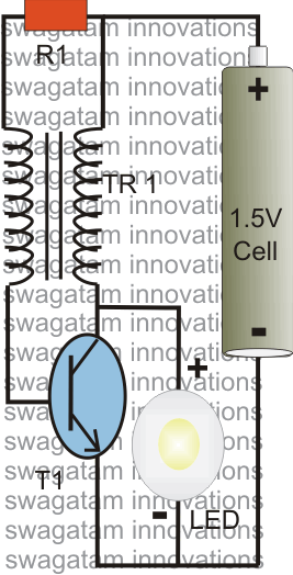
The post explains a simple 1 watt LED driver circuit using a single 1.5 V penlight cell through the joule thief concept. The coil may be wound over a T13 toroidal ferrite core using 0.2 mm or 0.3 mm...
Warning: include(partials/cookie-banner.php): Failed to open stream: Permission denied in /var/www/html/nextgr/view-circuit.php on line 713
Warning: include(): Failed opening 'partials/cookie-banner.php' for inclusion (include_path='.:/usr/share/php') in /var/www/html/nextgr/view-circuit.php on line 713