
Modular Burglar Alarm

The described circuit operates as an automated security system with specific functionalities aimed at managing entry and exit delays while ensuring user safety. The circuit is powered by a continuous 12-volt supply, making it suitable for integration into various environments where reliable power is available. The switch SW1 serves as the primary control mechanism for enabling the system. When SW1 is opened, it activates the circuit, allowing for a designated exit period.
The system incorporates both normally-closed and normally-open contacts, providing versatility in installation depending on the specific requirements of the environment. This feature allows for compatibility with a variety of sensors and alarms, enhancing the security setup. The inclusion of a 24-hour Personal Attack/Tamper zone adds an additional layer of security, ensuring that any unauthorized access or tampering is promptly detected.
The circuit utilizes green LEDs as visual indicators to confirm system readiness. Prior to opening SW1, all LEDs should be illuminated, signaling that the system is in a stable state. Once SW1 is activated, the user has a limited time frame—approximately one minute—to exit the premises. During this exit period, an audible alert from the Buzzer serves as a reminder to the user, ceasing only when the door is closed, which signals the completion of the exit process.
Upon re-entry into the building, the user is again afforded a one-minute window to deactivate the system by switching SW1 off. Failure to do so within the allotted time results in the energization of a relay, which may trigger additional security measures or alerts, depending on the overall system configuration. The circuit's design allows for the integration of expansion modules, enabling the addition of various zones, including those equipped with inertia (shock) sensors, further expanding its functionality and adaptability to different security needs.This circuit features automatic Exit and Entry delays and a timed Bell Cut-off. It has provision for both normally-closed and normally-open contacts, and a 24-hour Personal Attack/Tamper zone. It is connected permanently to the 12-volt supply and its operation is "enabled" by opening SW1. By using the expansion modules, you can add as many zones as you require; some or all of which may be the inertia (shock) sensor type.
All the green LEDs should be lighting before you open SW1. You then have up to about a minute to leave the building. As you do so, the Buzzer will sound. It should stop sounding when you shut the door behind you. This indicates that the Exit/Entry loop has been successfully restored within the time allowed. When you re-enter the building you have up to about a minute to move SW1 to the off position. If SW1 is not switched off in time, the relay will energise and s 🔗 External reference
Related Circuits

Infrared Intruder Alarm Circuit. This circuit alerts the presence of a trespasser using an infrared system or Infrared Intruder Alarm circuit, which is quite interesting. It activates when there is an intrusion detected. The Infrared Intruder Alarm circuit operates by...
This circuit can be constructed using easily accessible, low-cost components, some of which might even be found in a collection of spare parts. The circuit in question is designed to utilize common electronic components, making it an ideal project for...

The digital time clock circuit is of great interest to electronic amateurs. The most popular clock ICs include the LM8361 and MM5387. Unfortunately, these ICs... The digital time clock circuit serves as an essential component for various electronic applications, providing...
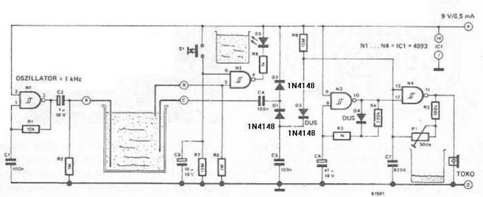
The circuit diagram is straightforward and operates as follows: the N1 Schmitt trigger functions as an oscillator, producing a frequency of approximately 1 kHz. When there is sufficient water in the tank, alternating voltage flows from electrode A to...
This circuit illustrates the NE555 timer used in a light-sensitive alarm sensor circuit diagram. Features include the ability to detect a sudden shadow falling on the sensor. The NE555 timer is a versatile integrated circuit widely utilized in various timing,...
This circuit is permanently plugged into a mains socket and NI-CD batteries are trickle-charged. When a power outage occurs, the lamp automatically illuminates. Instead of illuminating a lamp, an alarm sounder can be chosen. When power supply is restored,...