
Modulation monitor

The broad-tuned receiver operates by utilizing a loosely coupled wire antenna, which is strategically positioned in proximity to the transmitting antenna. This setup allows the receiver to capture a wide range of radio frequency (RF) signals effectively. The loosely coupled wire acts as an inductive element, enabling the receiver to demodulate various RF signals without the need for precise tuning to a specific frequency.
In a typical configuration, the broad-tuned receiver includes components such as an RF amplifier, a demodulator, and audio output circuitry. The RF amplifier enhances the weak RF signals received by the wire antenna, ensuring that they are strong enough for subsequent processing. The demodulator then extracts the original information signal from the modulated RF carrier wave, converting it into a baseband audio signal or another form suitable for further use.
The design of the receiver may incorporate various filtering techniques to minimize noise and interference, thus improving the clarity of the demodulated signal. Additionally, the output stage may include audio amplification to drive speakers or headphones, allowing for audible reproduction of the received signals.
Overall, the broad-tuned receiver is an efficient solution for applications requiring the reception of diverse RF signals in environments where precise frequency tuning is not feasible. It is particularly useful in scenarios such as amateur radio, emergency communication systems, and educational demonstrations in the field of electronics.Broad-tuned receiver demodulates the RF signal picked up by a ioosely coupled wire placed near the transmitting antenna. 🔗 External reference
Related Circuits

Tom Au-Yeung and Wilson Tang from Maxim Integrated Products describe a method to create a wireless temperature monitoring system using two integrated circuits (ICs). This system can be designed utilizing a local temperature sensor along with an amplitude-shift-keying (ASK)...

Heart rate monitor using an 8051 microcontroller. It measures the heart rate from the fingertip using an IR diode and phototransistor pair (Photoplethysmography). The AT89S51 microcontroller is utilized in this application. The heart rate monitor circuit operates based on the...
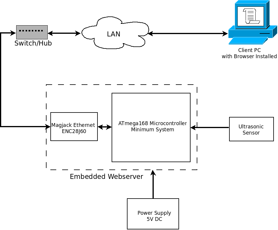
Throughout this year, significant attention has been dedicated to the development of an embedded web server device, a concept that has long been envisioned. This idea is not entirely original; it builds upon existing developments and references available on...

As shown in the generator start battery automatic monitor circuit diagram. The generator start battery automatic monitor circuit is designed to oversee the battery's status during generator operation. This circuit ensures that the battery remains charged and functional, preventing premature...
A reason to modulate a message signal is to match the communication channel's frequency. This is necessary because the information to be sent over the channel is often at a relatively low frequency. For instance, the frequency range of...

Works on AVR controllers with RAM and a hardware UART. This code is easily modified to integrate with ROM applications to provide the ability to monitor and interact with ROM applications via a terminal simulation program over an RS-232...