
modulation
In an amplitude modulation (AM) system, the modulation process is critical for adapting low-frequency information signals for effective transmission over communication channels. The carrier wave, which operates at a much higher frequency, serves as the basis for conveying the message signal. The modulation process involves varying the amplitude of the carrier wave in accordance with the instantaneous amplitude of the message signal, thus creating a composite signal that can be transmitted over long distances while minimizing interference.
The mathematical representation of the message signal and its modulation is essential for understanding the system's performance. The modulation index, defined as the ratio of the peak amplitude of the message signal to the peak amplitude of the carrier wave, plays a pivotal role in determining the quality of the transmitted signal. Maintaining the modulation index below 1 ensures that the envelope of the modulated signal accurately reflects the original message, thus facilitating easier demodulation at the receiving end.
The envelope detector, a fundamental component in the demodulation process, utilizes a diode to rectify the modulated signal, allowing only the positive half-cycles to pass. The subsequent low-pass filter, composed of a resistor and capacitor, smooths out the rectified signal, effectively reconstructing the original message signal. The design parameters of the envelope detector, including the values of the resistor and capacitor, must be carefully selected to ensure that the cutoff frequency of the low-pass filter is appropriate for the bandwidth of the message signal, thereby optimizing the recovery of the original information.
In practical applications, AM remains prevalent in various broadcasting technologies, including radio and television. The robustness of AM against certain types of interference, combined with its simplicity in implementation, ensures that it continues to be a valuable method for transmitting audio and visual information across diverse platforms. Understanding the principles of amplitude modulation and the design of associated circuits is crucial for engineers working in the field of communications and signal processing.As mentioned before, a reason to modulate a message signal is to match the communication`s channel frequency. The reason for this is that information to be send over the channel is often at a rather low frequency.
For example, the sound of music range in frequency from about 100 to 15, 000 Hz. It is very difficult to send such low-frequency signals over great distance. Low frequency signals will be interfered by other similar signals. There are many techniques for modulation. The technique that we will emphasis on is standard amplitude modulation. There are also many other modulations including methods using frequency and phase. In amplitude modulation, the circuit or the modulator combines the carrier wave (Fig 1) and the message signal (Fig 2) to form a modulated wave (Fig 3) that is a carrier wave with change in amplitude. The frequency that I choose for the figures is for examples only. In reality, the value of the frequency is higher. The message signal is a cosine wave or a sine wave. In another word, the message signal is a sinusoidal wave function. This is the same for a carrier wave except its frequency is very large when compare to the frequency of the message signal.
Let us use mathematical terms to relate our signals. For the message signal in the above example, the following mathematical expression represents it. The constant Ka is the amplitude sensitivity of the modulator or the transmitter. The amplitude of equation 3 is called the envelope of the AM wave. We can represent that as a(t). The percentage of modulation will depend on the absolute value of Ka*m(t). If the absolute value of Ka*m(t) is less or equal to 1 for all t, then the percentage of modulation is less than or equal to 100%. However, if the absolute value of Ka*m(t) is greater than 1 for some t, then the percent of modulation is in excess of 100% or overmodulation.
The following table summarizes the modulation percentage. For example, assume that the value of |Ka*m(t)| is 0. 7, then the percentage of modulation is 70%. Therefore, if |Ka*m(t)| is 1. 1, then the percentage of modulation is 110%. If the percentage of modulation is less than or equal to 100%, then the demodulation circuit used to recover the message signal from the incoming AM wave is greatly simplified. There are two conditions to be satisfied in order to produce an a(t) or envelope of the modulated wave to be the same shape as the message signal m(t).
The first condition is that the percentage of modulation is less than 100% so the envelope or a(t) is not distorted. The second condition is that the message bandwidth is small compared to the carrier`s frequency. The demodulation circuit for the envelope is called the envelope detector. It is just basically a low-pass filter consists of a resistor, a capacitor and a diode. Figure 4 shows a simple circuit diagram of the envelope detector. The above circuit diagram is a low pass filter which just consists of a capacitor and resistor. The purpose of a low pass filter is to allow low frequency component of the s(t) or the modulated wave to pass to the output while the high frequency component is filter out in the process.
The values of the resistor and the capacitor determine how low the frequency will be able to appear at the output. Amplitude modulation is still in used today. Some its usage is AM broadcast radio stations. AM is still used in television broadcasting as a method for transmission of picture information while the sound is done by FM.
🔗 External reference
Related Circuits
The circuit depicted in figure 2-6 and discussed in previous sections serves illustrative purposes only and is not practical in real-world applications. Nevertheless, the fundamental principle involved—the variation in reactance of an oscillator circuit in response to modulating voltage—represents...
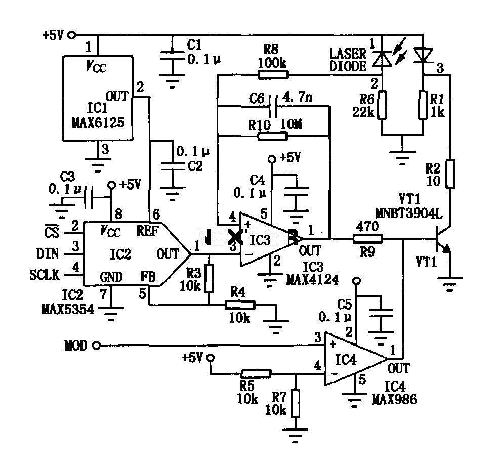
The laser tube drive circuit typically incorporates a photodiode that generates a laser beam proportional to the intensity (optical power) of the current. However, this type of photocell is generally slow and unable to track modulation effectively, particularly for...
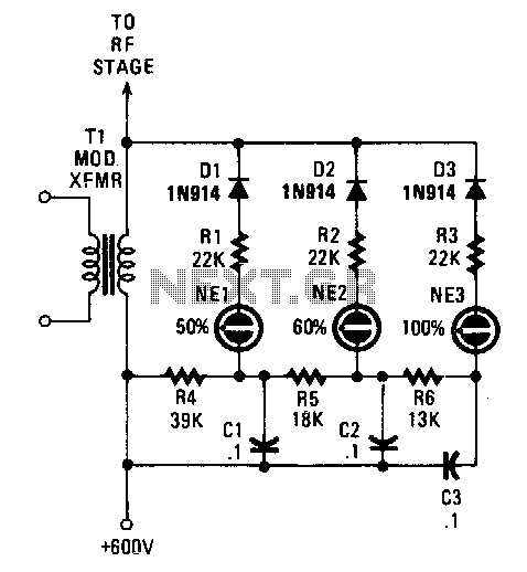
Switching diodes are utilized to activate the neon lamps when negative-peak modulation reaches 50%, 60%, and 100%. To operate the circuit effectively, it is important to monitor the lamps. The 50% lamp should ideally be firing continuously, the 60%...
To understand how the 74AC14 PWM circuit functions, it is essential to focus on the schematic section that includes the trimpot, diodes, capacitor, and the first inverter logic gate. Initially, when power is applied to the circuit, the capacitor...
The circuit was designed to obtain signals through amplitude modulation, exhibiting good sensitivity and selectivity. Amplitude modulation. The amplitude modulation (AM) circuit is engineered to effectively capture and process radio frequency signals. The design focuses on achieving high sensitivity, allowing...
This is an FSK modulation circuit composed of the 74LS74. The FSK modulation circuit does not include a phase-locked loop (PLL) or a high-Q bandpass filter, eliminating the need for tuning adjustments in the high-frequency modulation circuit. The two...