
I/O monitor program for AVR
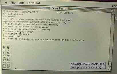
The described circuit operates on AVR microcontrollers equipped with RAM and a hardware UART interface. The primary functionality of this system is to facilitate communication with ROM applications through a terminal simulation over an RS-232 interface. This capability is essential for monitoring and interacting with embedded systems in real-time, providing invaluable insights during the development and debugging phases.
The system's architecture allows for the monitoring and manipulation of memory and I/O registers, specifically within the address range of $0000 to $00FF. This range encompasses both the register array and I/O spaces, enabling developers to inspect and modify the state of the microcontroller dynamically. The ability to change values in memory while the controller is operational significantly enhances debugging efficiency, as it allows for immediate feedback on the effects of changes made to the system.
For applications requiring adaptation to microcontrollers with wider stack pointers, it is crucial to ensure proper initialization of both the low (SPL) and high (SPH) byte registers of the stack pointer. The provided assembly code snippets illustrate the initialization process by loading the low and high bytes of the highest RAM address (defined by `ramend`) into the corresponding stack pointer registers. This step is vital for maintaining system stability and ensuring accurate stack operations.
The command set of the monitor allows for comprehensive control over memory operations, including reading and writing data byte-by-byte. This feature is particularly useful for developers aiming to test specific functionalities or to validate the integrity of data stored in the microcontroller's memory and I/O registers. Overall, this setup serves as a robust tool for embedded system development, offering a combination of monitoring, debugging, and interaction capabilities essential for efficient hardware and software integration.Works on AVR controllers with RAM and a hardware UART. This code is easily modified to integrate with ROM applications to provide the ability to monitor and interact with ROM applications via an terminal simulation program over an RS-232 port. It can also be used to stimulate and monitor I/O to aid in debugging hardware. It is very helpful to be able to look around at memory, I/O and peripherals, and change things inside a running controller
If you adapt this to a controller with a stack pointer that is more than 8 bits wide, be sure that both registers in the stack pointer, both spl and sph, are initialized. As an example ldi temp,low(ramend) ;get low byte of highest RAM address for this chip. out spl,temp ;set spl ldi temp,high(ramend) ;get low byte of highest RAM address for this chip.
out sph,temp ;set spl The monitor's commands allow reading, monitoring, and byte-by-byte modification of memory locations $0000 through $00FF, which includes the register array and I/O space. 🔗 External reference
Related Circuits
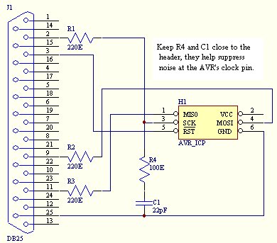
An In Circuit Programmer is a very valuable tool. Not only does it allow you to program your AVR's with ease, you can update your program without having to remove the AVR (very useful when working with surface mount...
Read and write raw data from an SD card using a computer without a microprocessor, bypassing the FAT32 file system. The goal is to create a C script that can store specific parameters on the SD card for future...
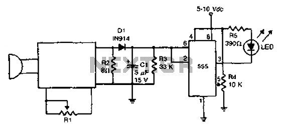
The acoustic detector consists of a Schmitt trigger IC555 connected to various components. When the input exceeds a certain voltage, the output will change state from high to low. R4 is used to set the threshold voltage. The acoustic detector...
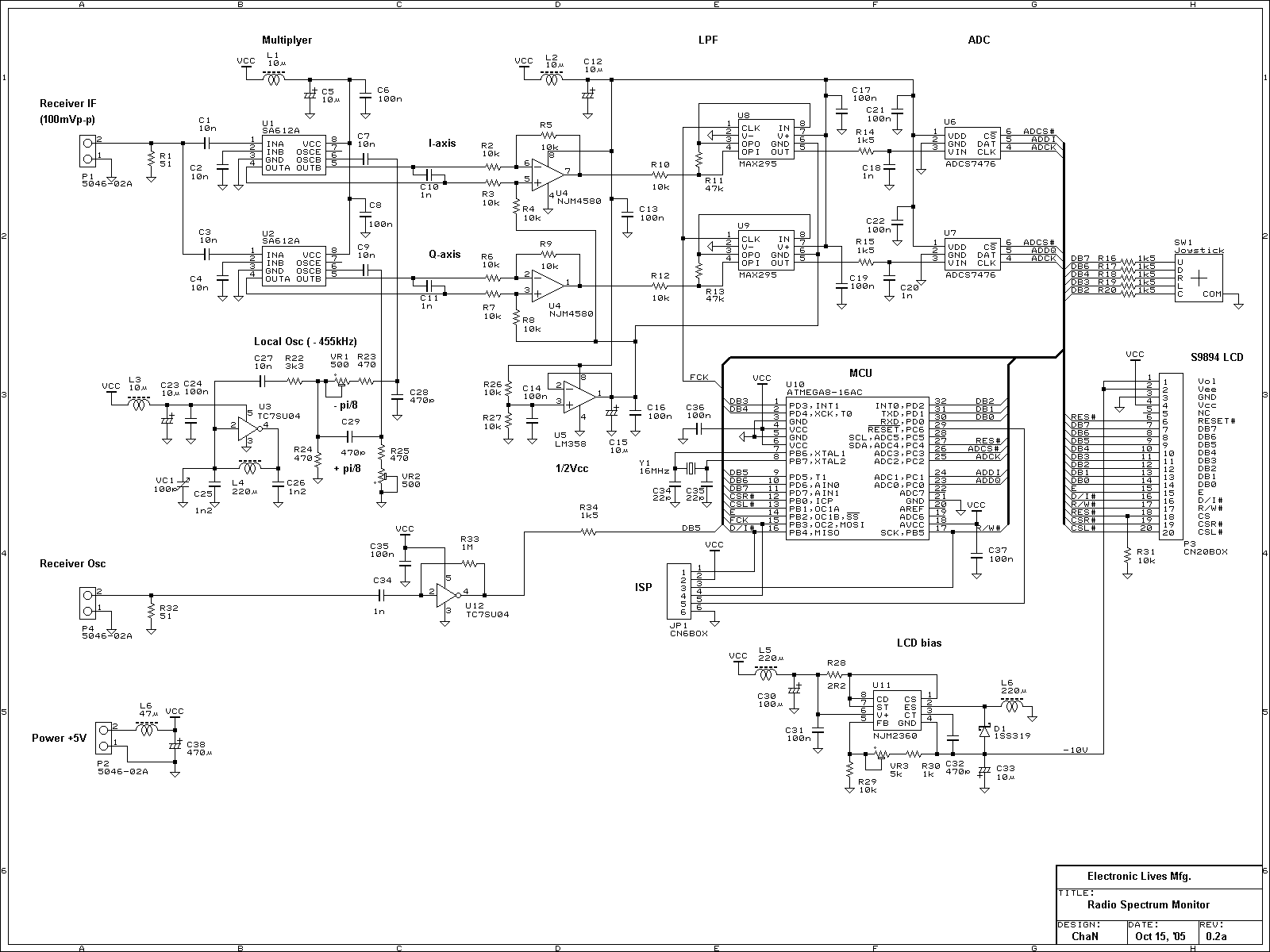
This is an experimental work to monitor a spectrum pattern of radio band, and is a continuous project from Audio Spectrum Monitor. To analyze the spectrum of an input signal, I chose an Atmel's AVR microcontroller used in Audio...
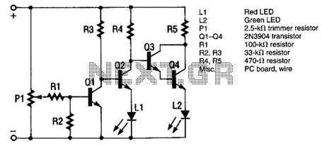
The monitor functions as a basic voltage comparator, utilizing a car battery as its power source. The input voltage to the comparator is adjusted using potentiometer PI. This adjustment ensures that the green LED L2 illuminates when the alternator...
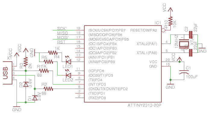
This is a low-cost AVR programmer using the ATtiny2313. The schematic diagram is provided below. First, set up the circuit as shown. One important consideration is to configure the fuse bits using the command: avrdude -c usbasp -p t2313...