
monitor an input pulse train
The missing pulse detector circuit is primarily based on the 555 timer IC configured in a monostable mode. In this configuration, the 555 timer generates a single output pulse when triggered by an input signal. The circuit continuously monitors the input pulse train from the IR sensor, which is activated by the remote control. The IR sensor outputs a series of pulses as long as the IR beam is uninterrupted.
When the IR beam is obstructed, indicating a missed pulse, the 555 timer's output transitions from a high state to a low state. This transition serves as a notification to the Basic Stamp microcontroller, which can then execute a predetermined response based on the missing pulse event. The circuit's design includes a resistor (R2) that must be calibrated to account for variations in the remote control buttons, ensuring reliable detection of pulse interruptions.
Incorporating additional components such as capacitors may enhance the circuit's stability and response time. The specific values of the resistors and capacitors can be calculated based on the desired timing characteristics of the pulse detection. Additionally, a diode may be included to protect the circuit from reverse polarity or voltage spikes that could occur from the IR sensor's output.
Overall, the missing pulse detector is a valuable component for applications requiring real-time monitoring of pulse signals, allowing for responsive actions when interruptions occur. This circuit exemplifies the integration of traditional electronic components in modern applications, showcasing the versatility and functionality of the 555 timer IC in pulse detection scenarios.This circuit is a missing pulse detector. It is used in the_ General Purpose Controller Board with Basic Stamp 1. This circuit is used to monitor an input pulse train, and when a pulse is missed the 555 timer output will switch low. For the General Purpose Controller Board the input pulses are provided from an IR sensor salvaged from an old VCR.
A n "All In One Remote" is used to trigger the IR sensor continuously by clamping one of the remote buttons down, which causes the remote to transmit continuously. When the IR beam is broken by someone walking past it the missing pulse circuit produces an output to the Basic Stamp.
R2 must be adjusted differently for different buttons on the remote. 🔗 External reference
Related Circuits

By utilizing a 556 dual timer, with IC1A functioning as a waveshaper and IC1B as a pulse generator, a pulse width range of 10:1 can be achieved. This circuit can be triggered using a sine wave. The circuit operates on...

The structure and working principle of this circuit are fundamentally similar to the previous circuit, with some variations in the components used. The circuit is divided into seven bands, with center frequencies selected at 60 Hz, 150 Hz, 400...
The relaxation oscillator generates a relatively consistent square wave. By altering the duty cycle, the effect can be visualized using LEDs. The following variation of the relaxation oscillator circuit can be assembled. The relaxation oscillator circuit typically consists of a...

There are several methods to input a signal into the NE602. Simple untuned approaches (a and b) are viable. For tuning to a specific frequency, an LC resonant circuit with ungrounded trimmer capacitors (c and d) or grounded variable...

The portable hypoxia monitoring circuit comprises the oxygen sensor OS-12, a DC amplifier IC1, an A/D converter IC4, and a liquid crystal display F2100-34PI. Additionally, it includes a voltage comparator IC2 and a positive and negative power converter IC,...
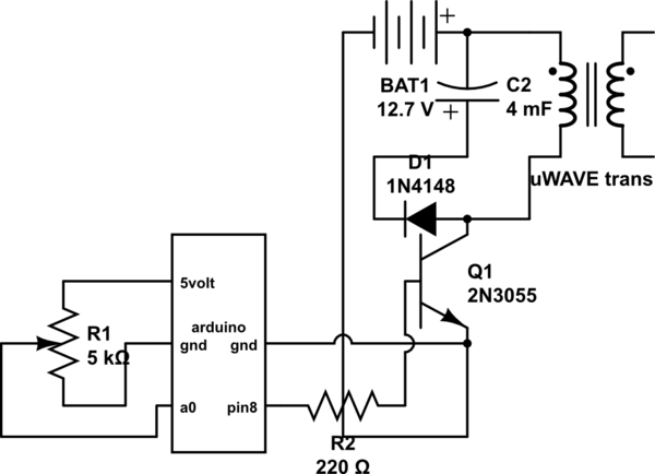
If both devices need to be powered from the battery, should the emitter be connected to the ground of the Arduino and the battery to prevent current from flowing through the Arduino ground, ensuring a clean pulse? Alternatively, can...