
Pulse Generator Circuit

The circuit operates on the principle of using a 556 dual timer, which contains two independent timer circuits. IC1A is configured as a waveshaper, transforming the incoming sine wave signal into a square wave. This transformation is essential for generating consistent pulse widths, which are crucial in various applications such as timing and frequency modulation.
IC1B is set up as a pulse generator that takes the output from IC1A. The pulse width generated by IC1B can be adjusted within a 10:1 ratio, allowing for flexibility in the duration of the output pulses. This feature is particularly useful in applications where different timing intervals are required, such as in signal modulation or timing circuits.
The circuit can be triggered by an external sine wave source, which is fed into the input of IC1A. The dual timer's configuration ensures that the output pulse widths can be fine-tuned according to the specific needs of the application. The output can be used to drive various electronic components, such as LEDs, relays, or other digital circuits.
In summary, this 556 dual timer circuit provides a versatile solution for generating pulse widths with a significant range, leveraging the dual functionality of the timer ICs for effective signal processing. By using a 556 dual timer with IC1A acting as a waveshaper and 1C1B as a pulse generator, a 10:1 range of pulse widths can be generated. A sine wave can be used to trigger this circuit. 🔗 External reference
Related Circuits
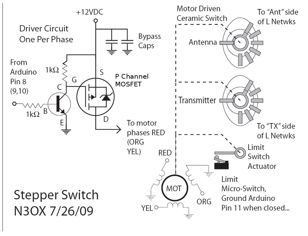
Information is needed regarding a circuit to manage the Remote Coax Ameritron RCS-10, as no diagram can be found on Google. The Ameritron RCS-10 is a remote coax switch designed for amateur radio applications, allowing users to control multiple antennas...
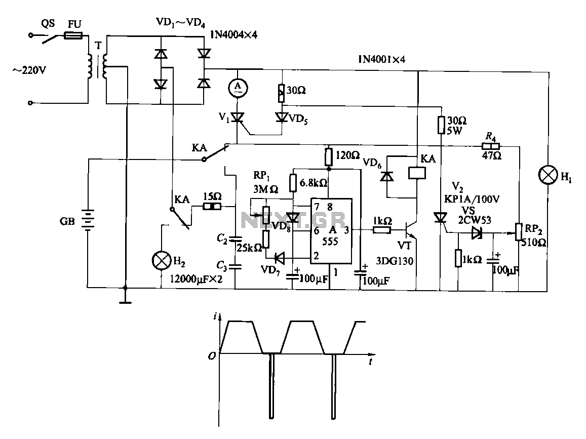
Fast and efficient charging is significantly higher than conventional charging, achieving a current charge that is ten to several times greater. When the battery voltage reaches a predetermined level (known as the polarization point), polarization within the cell becomes...
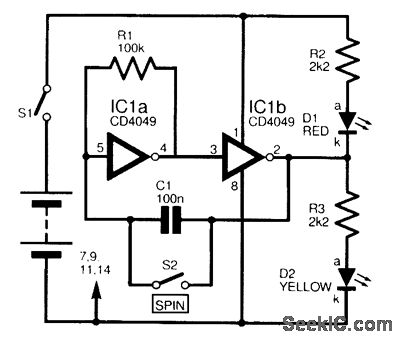
This circuit is designed to electronically simulate the tossing of a coin using a 4049 hex inverter integrated circuit (IC). It employs two of these ICs, specifically IC1a and IC1b, which are configured as an astable oscillator. This configuration...
This is a straightforward tester designed to verify the fundamental operations of an infrared remote control unit. It is cost-effective and simple to assemble. The tester utilizes the infrared receiver module TSOP1738. The operation of the remote control is...
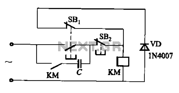
An AC contactor switch, when used with DC or pulse DC excitation, can minimize short circuit and core power consumption. This results in a significant reduction in the power consumption of the electromagnet, which can eliminate noise and reduce...
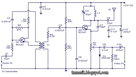
The TV transmitter circuit described utilizes UK standard 1 FM modulation for audio and PAL modulation for video. The audio signal intended for modulation is first amplified using transistor Q1 and its associated components. Transistor Q2 serves dual purposes:...