
WAH & FUZZ Guitar circuits

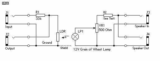
The Wah and Fuzz pedal modification involves a dual-channel volume control circuit that has been creatively repurposed. The original Morley circuit, which utilizes a Light Dependent Resistor (LDR) and Light Emitting Diode (LED) for control, serves as the foundation for this project. The LDR responds to light changes from the LED, enabling a variable resistance that affects the audio signal, thus creating the characteristic Wah effect.
The Wah circuit operates on the principle of phase shifting, achieved through an operational amplifier (op-amp) configuration. This design mimics the sound of traditional inductor-based Wah pedals while providing a more straightforward construction process. The absence of the up-and-down variation typically found in traditional pedals is compensated by focusing on the modulation of the LED's brightness, which in turn alters the LDR's resistance.
The Fuzz circuit, added to the Wah design, allows for a rich distortion effect that can be engaged or disengaged via a switch. This integration of two effects into a single unit enhances versatility, making it suitable for various musical styles. The switchable aspect is crucial for live performances, allowing musicians to easily toggle between effects without needing multiple pedals.
Overall, the combined Wah and Fuzz circuit provides a unique audio processing tool that leverages existing technologies while allowing for personal modification and enhancement. The careful selection of components and circuit design ensures both effects maintain high audio fidelity and usability, catering to the needs of guitarists seeking to expand their tonal palette.These two projects , Wah and Fuzz, are the results of a modification to a Morley dual channel volume control pedal that one of my sons suggested I undertake as He had no use for the volume unit but thought I could modify the pedal into a Wah unit. I decided later to add a Fuzz circuit and combine the two into a single switchable unit as described further on.
Not being one to re-invent the wheel, I downloaded several circuits from the Internet and after breadboarding severals I chose the original Morley circuit as it had the best sound and was using an LDR/LED control which simplified its construction. Using the phase shifting design with an op-amp sounds very close to the inductor type Wah circuit but with no up and down variation like the pedal allows . I concentrated on the triggering aspect of the LED/LCD to try and produce a varying attack and de 🔗 External reference
Related Circuits
The project described here is one that you can just build and have working straight away although it is entirely possible that you will want to experiment a bit, and requires only a small handful of parts. In its...
Leo Esaki invented the tunnel diode in 1957 while working at Sony (then known as Tokyo Tsushin Kogyo). Tunnel diodes feature a very narrow, heavily doped p-n junction approximately 10 nm wide, which exhibits a broken bandgap. This configuration...
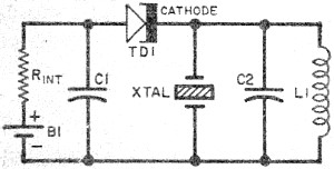
These two circuits are interesting from an academic point of view. Their practical implementation is rather critical and it is not easy to get steady operation. Circuit (a) requires a "cooked" zener: connect it first to a constant current...
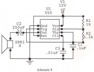
This circuit features an astable oscillator constructed around a 555 timer, generating an alarm tone of 1.8 kHz, which directly drives a speaker. It serves as a fundamental alarm circuit that can be utilized in various projects. Although the...
It is essential to consider migrating to PIC microcontrollers and exploring compilers such as those offered by Proton Smart, which include Sony IR and Philips RC5 codecs. This approach is particularly advisable for security-sensitive applications. Additionally, Bluetooth and Wi-Fi...
The MP3 files (up to 65,536) are stored on a micro SD card. This embedded MP3 module is a universal and compact circuit (37 mm x 27 mm) designed for playing MP3 audio files. The MP3 module can be...