
Mono preamp based on a NE5534
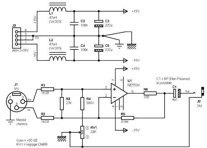
The NE5534-based mono preamplifier is designed to amplify low-level audio signals, making it ideal for use with dynamic or condenser microphones that have an output impedance between 200 ohms and 600 ohms. The circuit utilizes the NE5534 operational amplifier, known for its low noise and high-speed performance, which contributes to the overall quality of the audio signal.
The preamp achieves a gain of 50 dB, which is suitable for boosting microphone signals to line level without introducing significant distortion or noise. The bandwidth of approximately 25 kHz ensures that the preamplifier can handle a wide range of audio frequencies, making it effective for various audio applications, including recording and live sound reinforcement.
A split power supply is required to power the NE5534, typically providing both positive and negative voltage rails. This configuration allows the op-amp to handle AC audio signals effectively, ensuring that the output waveform remains centered around zero volts, which is crucial for maintaining signal integrity.
The circuit design may include additional components such as resistors and capacitors for setting the gain, filtering, and stability. Proper layout and grounding techniques are essential to minimize noise and interference, ensuring that the preamplifier performs optimally in various environments.
Overall, this NE5534 mono preamplifier is a reliable choice for audio applications requiring high gain and low noise, making it suitable for professional audio equipment and recording systems.Mono preamp based on a NE5534 circuit diagram. This preamp is particularly suitable for microphones with an output impedance of 200 ohms to 600 ohms. The advantage of the preamplifier is 50 dB, and bandwidth (-3 dB) extends to about 25 KHz. The splitted power supply is required. 🔗 External reference
Related Circuits
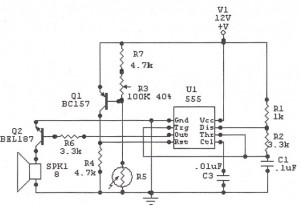
The following circuit illustrates a Sun Up Alarm Light Alarm Circuit Diagram. This circuit is based on the 555 Integrated Circuit (IC). Features include simplicity and cost-effectiveness. The Sun Up Alarm Light Alarm Circuit employs the 555 timer IC in...
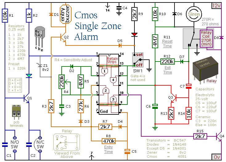
This circuit features automatic exit and entry delays, a timed bell cut-off, and a system reset. It accommodates both normally-open and normally-closed switches, making it compatible with various input devices such as pressure mats, magnetic reed contacts, foil tape,...
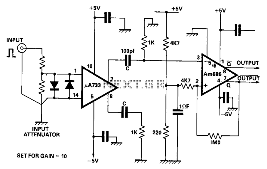
A video amplifier output arrives at a differentiation stage before the Schottky comparator. The typical propagation delay is reduced to 10 ns. The output pulse width is determined by the capacitance value, where C is 100 pF, resulting in...
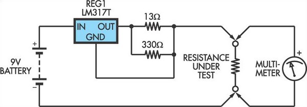
This adapter circuit functions as a 100mA constant current source. It is connected across a low-value resistor, the resistance of which is to be measured, and the resulting voltage drop can then be assessed using a digital multimeter (DMM)....
This circuit is mainly intended to provide common home stereo amplifiers with a microphone input. Using a stereo microphone the circuit must be doubled. In this case, two separate level controls are better than a dual-ganged stereo potentiometer. Low...
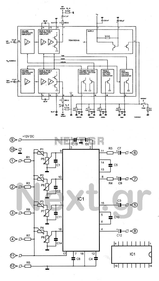
The circuit utilizes the TDA1524 chip, which is an integrated control unit for volume, bass, treble, and balance adjustments. Control is achieved through four potentiometers (P5-P8). The integrated circuit IC1 requires very few external components to operate. Potentiometers P1-P4...
Warning: include(partials/cookie-banner.php): Failed to open stream: Permission denied in /var/www/html/nextgr/view-circuit.php on line 713
Warning: include(): Failed opening 'partials/cookie-banner.php' for inclusion (include_path='.:/usr/share/php') in /var/www/html/nextgr/view-circuit.php on line 713