
Mono to stereo circuit
This circuit appears to describe a variable output voltage system, likely utilizing a potentiometer or a similar adjustable component. The output voltage is dependent on the input voltage (Vin) and varies based on the position of the adjustable component.
At the center position of the potentiometer, the output voltage is calculated to be 0.707 times the input voltage, indicating a specific attenuation of the signal. This could suggest that the circuit is designed to provide a stable reference voltage or a specific gain setting, often utilized in audio applications or signal processing where a controlled output is necessary.
At the extreme positions of the adjustable component, the output voltage equals the input voltage (Vin), allowing for full signal transmission without attenuation. This functionality indicates that the circuit is capable of operating as a variable gain amplifier or a voltage divider, depending on the configuration of the components in the circuit.
The overall design likely includes additional components such as resistors or capacitors to stabilize the output and prevent noise, ensuring that the voltage output remains consistent across the varying positions of the adjustable component. The circuit may also incorporate feedback mechanisms to enhance performance and linearity across the entire range of operation.
In summary, the described circuit is a versatile voltage output system, capable of providing both attenuated and full output levels based on the position of the adjustable component, making it suitable for applications requiring precise voltage control.The output voltage is = 0.707 x Vin, at the center posititon. The output voltage is = Vin, at either extreme position. 🔗 External reference
Related Circuits
This document outlines a CMOS circuit designed for time adjustment in a spot welder. The circuit allows for the selection of a number of cycles, ranging from 1 to 99, with practical applications typically using around 10 cycles. The...
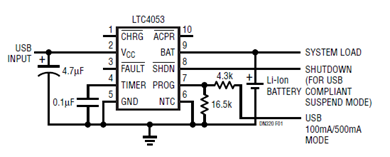
The schematic presented illustrates a minimal component solution for a USB battery charger utilizing the LTC4053 integrated circuit (IC) to create a fully compliant USB charger. This IC functions as a standalone linear charger designed for lithium-ion (Li-ion) batteries,...
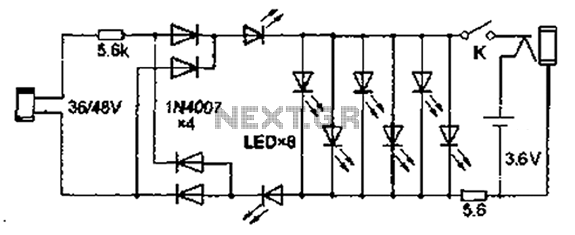
Also known as the Free lamp (commonly referred to as the Myanmar lamp by online sellers), this device operates using the voltage from a standard household fixed telephone line, eliminating the need for batteries or AC power. The lamp...
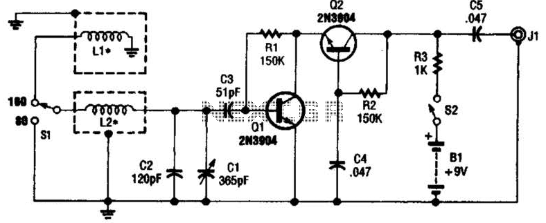
This antenna may assist in minimizing power-line noise. It consists of a plastic hula hoop or conduit with a diameter of 3 feet, which is covered with aluminum foil to serve as a shield for LI and L2. LI...
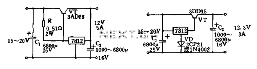
Expand integrated three-terminal regulator block circuit output current method The integrated three-terminal regulator is a versatile component commonly used in power supply circuits to provide a stable output voltage. This regulator typically consists of three terminals: input, output, and ground....
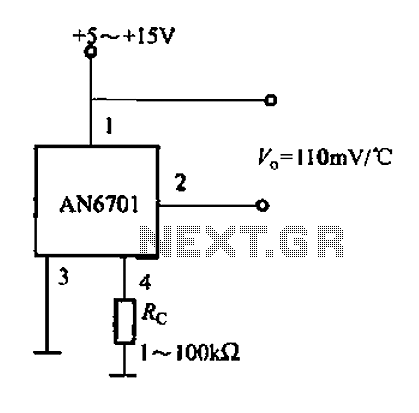
The AN6071 application circuit is illustrated. The relationship between the output voltage and temperature is 110 mV/°C. The AN6071 is a precision temperature sensor designed for applications requiring accurate temperature measurement and monitoring. The output voltage of the AN6071 varies...