
Mooring Light Controller
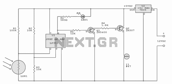
The circuit utilizes an operational amplifier (op-amp) configured as a comparator to regulate light levels based on ambient conditions. The op-amp chosen for this application can be either the LF351 or the 741, both of which are versatile and widely used in various electronic applications.
In this configuration, resistors R2 and R3 are employed to create a reference voltage of approximately 2.5 volts at the non-inverting input (pin 3) of the op-amp. This reference voltage serves as a threshold level against which the voltage at the inverting input (pin 2) is compared. The inverting input is connected to a light-dependent resistor (LDR1), which exhibits a variable resistance based on the intensity of light it receives. Under bright conditions, the resistance of the LDR drops to about 1000 ohms, while in darkness, it can increase significantly to around 1 megohm.
Resistor R1, valued at 100,000 ohms, is connected in series with the LDR to form a voltage divider. The voltage at pin 2 of the op-amp is determined by the voltage drop across the LDR and R1. When the ambient light level is high, the voltage across the LDR is comparatively low due to the low resistance, resulting in a voltage at pin 2 that remains below the 2.5-volt reference level at pin 3. In this state, the op-amp output at pin 6 is driven low, indicating that the light condition is sufficient and no action is required.
Conversely, when the light level decreases and the LDR resistance increases, the voltage drop across the LDR rises, potentially exceeding the reference voltage at pin 3. This change triggers the op-amp to switch its output state, allowing it to control additional circuitry such as a relay or a light source, thus providing a mechanism to turn on lights or activate other devices in response to low light conditions. The design effectively leverages the characteristics of the op-amp to create a reliable light-sensing circuit suitable for various applications in automation and control systems.Integrated-circuit U1-an LF351 or 741 op amp-is used as a comparator to control the light. Resistors R2 and R3 provide a reference voltage of about 2.5 volts at pin 3 of U1. When daylight falls on light-dependent resistor LDR1, its resistance is low: about 1000 ohms. In darkness, the LDR's resistance rises to about 1 megohm. Since R1 is 100,000 ohms, and the LDR in daylight is 1000 ohms, the voltage ratio is 100 to 1; the voltage drop across the LDR is less than the 2.5 volt reference voltage and pin 2 of U1 is held at that voltage. In that state, the output at pin 6 of U1 i 🔗 External reference
Related Circuits
In 1991, there was significant interest in a specific display technology that was difficult to find locally and expensive to import. Currently, this technology has become widely available and is considered obsolete due to the affordability and accessibility of...
The task involved testing the capacitive properties of food by connecting various edibles to an Arduino. This project, known as BeetBox, was developed by Scott Garner, a student at NYU-ITP, who designed an innovative musical instrument that uses beets...
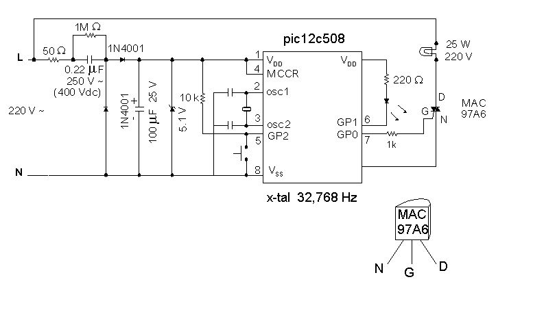
Introduction It is time for the 8-pin microcontroller Microchip PIC12C508, the SAVER V3.2, a new design of a device that controls a night light by turning it on and off. The SAVER V3.2 utilizes the Microchip PIC12C508 microcontroller, which features...
The title contains numerous words because this instructable integrates various concepts from multiple sources. The primary idea originated from Robomaniac's Desktop Energy Seed Lamp, combined with Witch's Growing Plants with LED Lights instructable and various wick gardening planters. The...
Application note on designing linear and switch-mode (switching DC-DC converter current source) battery charger applications that require external microcontrollers and related system-level issues for notebook computers. The application note provides guidance on the design of both linear and switching DC-DC...
Quasi square wave resonant converters, also referred to as quasi resonant (QR) converters, facilitate the design of flyback Switch Mode Power Supplies (SMPS) with diminished Electro Magnetic Interference (EMI) and enhanced efficiency. Due to their low noise generation, QR...