
Microcontroller projects 1

The circuit consists of several key components: the AT89S51/52 microcontroller, a 128x64 graphic LCD, the DS1302 real-time clock, and the LPC2103 microcontroller for USB connectivity. The AT89S51/52 interfaces with the graphic LCD to display time and other relevant information, while the DS1302 maintains accurate timekeeping with a backup capacitor. The LPC2103 serves as the main controller for USB communication, allowing for data exchange with a PC and management of switch and LED states.
The DS1302 is connected to a 32.768 kHz crystal oscillator, and the circuit includes pull-up resistors to ensure proper signal levels for the microcontroller. The USB connection is implemented using a standard USB cable, with power regulation achieved through the LM1117-3.3 voltage regulator to supply stable voltage levels to the microcontrollers. The design incorporates a feedback mechanism for the ADC, utilizing the trimmer potentiometer to scale the input voltage appropriately for accurate readings. The system’s architecture supports robust communication protocols, enabling real-time monitoring and control through the PC interface.
This project exemplifies a comprehensive integration of microcontroller technology, real-time clock functionality, and USB communication, resulting in a versatile and effective electronic measurement solution.In 1991, I was very interested on this display but I can`t find one in the town and expensive to import from abroad. But now, it`s everywhere and I can say that this technology is obsolete since the colorful TFT display is easy to find and cheap.
The mcu is AT89S51/52, connected to a 128x64 graphic LCD and time keeper DS1302. Many manufacturers pr oduce this LCD so be careful of differentpinout, refer toits original datasheet. DS1302 with trickle-chargeable to charge the backup battery connected to it, in this project I use a 1F/5. 5V. Yes, one Farad capacitor. After weeks charged, I test the backup function by disconnecting the power supplyfor a month, hohooo the time is still correct and continuously counting.
So if you want to safe a little money, I recommend you to use smaller capacitor like 0. 47F or 0. 33F. The crystal quality for DS1302 is very substantial, the small frequency error will lead to accumulated time drift. Pull up resistors area must, you`ll face a strange circuit behaviour if not installed. Need USB solution for your project Use LPC2148 MCU. In old days it`s very handy using LPT or COM to interface your project to PC but today they are vanished just like dinosaur.
All switch status can be monitored on the PC, as well as the ADC value. The LEDs are turn on/off by the first byte sent from PC. In my project input and output buffer size are 4 bytes each, you can increase the buffer depends on your need. To me, this project is about perfect because the program on PC can recover the connectionwhen temporary USB cable disconnection occurs.
The VB program recognize the device from its Vendor ID (C251) and Product ID (1301). Thiscircuit work onpoll-based communication, meaning theMCU will reply when receive request fromPC. So when USB disconnected, there is no update on LCD. There are 8 switches pulled-up by 10k resistors and8 LEDs with 120ohmseries current reducer so that the GPIO will not burn out by the overload sink current. Power comes from USB +5V, regulated down to 3. 3V by LM1117-3. 3. It`s very handy, isn`t it USB connection provides both data link and power supply. Just put in your consideration that the +5V is limited to 500-1000mA, depends on the PC/notebook/netbook type.
Some older notebook even limit the current up to 100mA only. If your project require big current, it`s wise to prepare an external power supply. Just like the USB external harddisk configuration, when the PC power is insufficient the harddisk should be connected to 2 USB ports or using external 5V power. Finally after a few days, my ARM7 voltmeter has been completed. It really gives me a relieved feeling after passing some hardware and software obstacle. Because I use the ready made LPC2103 module, I have to program it using USB ULINKwhich in my case interfere the mcu reset.
Till I disconnect the USB ULINK each time before reset the module. When copying code from LPC2148 project to LPC2103, there are some different register naming which takes time to fix, too. I use this voltmeter in combination with 500W DC/AC inverter, 12V accumulator, 12V 3A automatic charger.
During day time I charge the battery until the voltage reach 14. 2V, the charger will stop charging automatically. If the grid power down during dark time, I turn on the inverter for energizing the lighting. By having the voltage indicator, I can estimate the remaining operating hours of the battery. Actually the inverter will automatically shutdown if the voltage drop below 10V. LPC2103 is a small package mcu with only 48 pins. What I don`t like with this mcuis it uses 2 power supply: 1. 8V and 3. 3V, for mcu core and IO. Power comes from the 12V accumulator and at the same time mcu measure the voltage on AD0. 1 pin 33. I set the ADC working on 10-bit burst mode. Since the Vref is 3. 3V, the ADCmaximum count is 1023 when receiving 3. 3V. In order to scale the down 0-16V down to 0-3. 3, I use a 10k trimmer potentio 🔗 External reference
Related Circuits
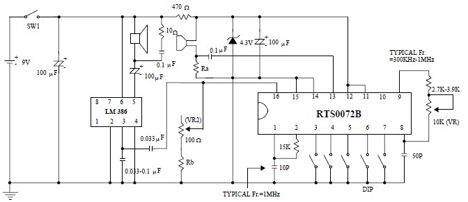
This voice changer circuit diagram is an electronic project developed using the RTS0072B single-chip CMOS LSI, specifically designed for voice-changing applications. It can transpose or distort one voice into another by encoding the input audio signals at normal speed...
Many microcontroller designs typically integrate various interfacing methods. A microcontroller (µC) system can be viewed as a system that reads from inputs. Microcontroller systems are versatile platforms that facilitate the integration of multiple interfacing methods to interact with various peripherals...
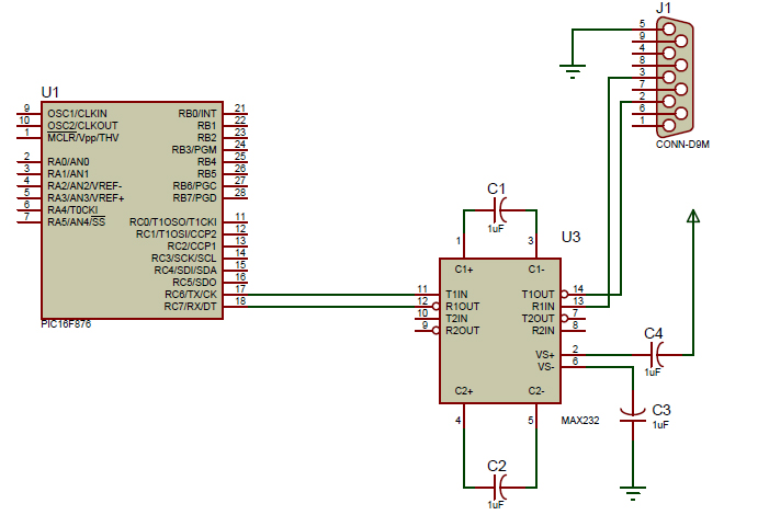
An introductory post on how to use serial communication in PIC Microcontrollers to send data to a PC. When considering serial communication, the primary thought is the transmission of data in a sequential manner. Until now, the focus has...
The Xminilab-B oscilloscope is based on the Atmel AVR ATXMEGA32A4 microcontroller. It is designed as a debug board by the Gabotronis company, as noted on rlocman.ru. The Xminilab-B oscilloscope features a compact and efficient design that leverages the capabilities of...
INTRODUCTION It is essential to monitor the operation of nearly all automated and semi-automated devices, such as washing machines and autonomous systems. Monitoring the functionality of automated and semi-automated devices is crucial for ensuring optimal performance and reliability. This can...
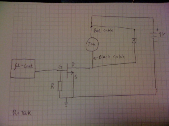
Control a fan using an LM34 temperature sensor and a computer fan with model number ASB0912L. A 2N7000 MOSFET transistor is utilized as a switch. The fan is intended to operate at a 35% duty cycle when the temperature...