
More debugging of the NRI 832
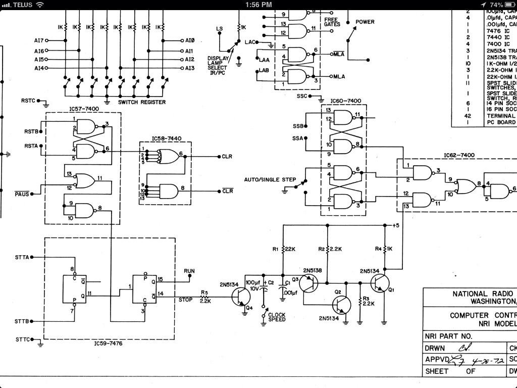
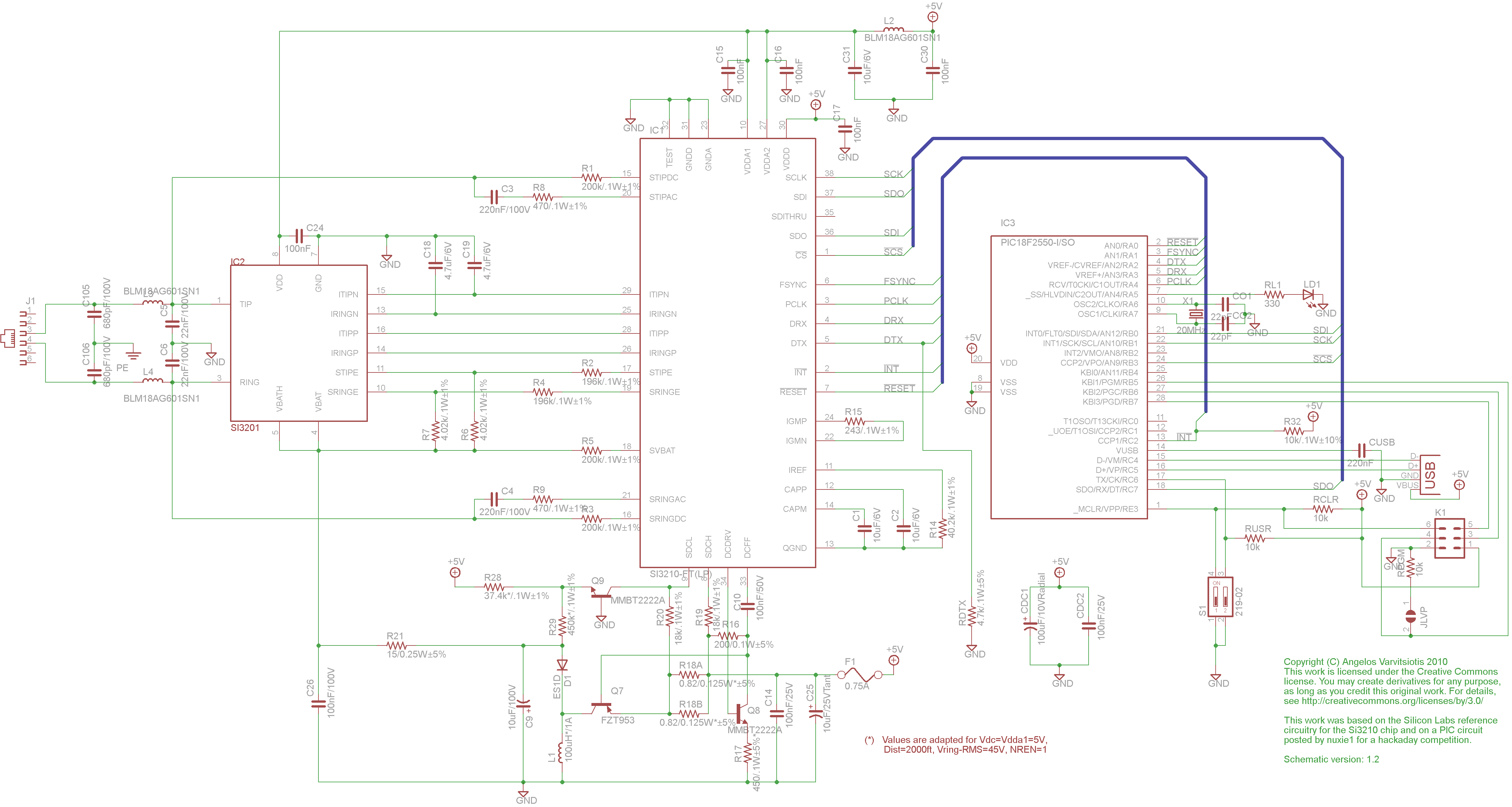
The circuit design involves a 555 timer configured in astable mode to produce a continuous square wave output at 6 kHz. This output serves as a clock signal for the 832 unit, facilitating synchronization of various components. The configuration of the 555 timer requires precise resistor and capacitor values to achieve the desired frequency. The transistors Q2 and Q3 are arranged in a manner that allows for the amplification of the timer's output, ensuring that the signal is strong enough to drive subsequent circuitry without degradation.
Transistor Q1's role as a buffer is crucial, as it isolates the oscillator's output from the load, preventing any potential feedback that could destabilize the oscillator's operation. The inclusion of Q4, controlled by the STOP signal from IC59, adds a layer of control to the oscillator's functionality, allowing the circuit to halt operation during specific conditions, such as when a halt instruction is executed or when the reset button is pressed.
The need to revert past modifications indicates that the circuit may have undergone multiple iterations, which can complicate troubleshooting and performance verification. Aligning the circuit with the original schematic is a strategic move to ensure that all components function as intended.
The decision to replicate the circuit on a stripboard is a practical approach, allowing for physical testing and verification of the design. If capacitor C1 is indeed faulty, it could prevent the oscillator from functioning correctly, as capacitors are integral to timing circuits. Testing for this fault will be essential in confirming the oscillator's reliability.
Simulating the circuit in LTSpice may provide a more accurate representation of its behavior compared to previous attempts with iCircuit. LTSpice is known for its robust simulation capabilities, which may yield insights into the circuit's dynamics and help identify any discrepancies between theoretical and actual performance.I`ve made more headway. The other day I built a 6kHz oscillator using a 555 to produce a clock signal that I could inject into the 832. You can see the trace on the scope, and the oscillator itself pictured below. While running on the new clock, the rest of the machine seems to function properly. It`s hard to verify at 6kHz, the status of the accu mulator changes too fast to see. You can however see the program counter going. That is in the above YouTube video. Some more below the link. The oscillator proper consists of Q2 and Q3. Q1 functions as an amplifier to buffer the output. Q4 is driven by the STOP signal from IC59. When a HLT instruction is executed, or the reset button is depressed, the STOP line goes high, pulling that side of the oscillator to ground stopping it. A fair bit of work thus far has gone to undoing some past modifications that had been made to the circuit.
Right now, it`s pretty much in line with the schematic. I think my next step may be to duplicate the schematic circuit on a piece of stripboard and see if it behaves. I`m suspicious that C1 is dead. That would definitely kill the oscillator. My attempts at simulating the oscillator on my iPad in iCircuit have been less helpful than hoped. The oscillator seems to run at 128Hz no matter what I change. That is thoroughly wonky. I will try doing it in LTSpice and see if it behaves better. 🔗 External reference
Related Circuits
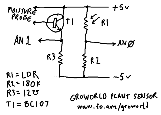
The plan is to implement plant sensing technology for a Groworld installation at Camp Pixelache. The circuitry has been enhanced for durability through soldering. The circuit diagram's component values are influenced by available surplus and donated stock but are...
This circuit gradually illuminates a 120VAC lamp over an approximate 20-minute period. A bridge rectifier converts the AC voltage to 120V DC, supplying power to the MOSFET and the 60-watt lamp. A 6.2K, 5-watt resistor along with a Zener...
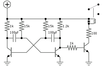
Powering this circuit with a 6V alkaline battery operates effectively with 100µF capacitors. However, there is an issue when attempting to replace the LED with a DPDT relay; a 6V relay previously available does not activate. Additionally, when using...
This page discusses the differences between assembled Open USB FXS dongle boards and DIY boards. While the assembled boards are fully tested and quality control approved, DIY boards may encounter various issues during assembly. Fortunately, most of these issues...
A project for a morning or sunrise alarm circuit that generates a beep-beep alarm sound and flashes an LED in response to sunlight. This sunrise alarm circuit is designed to provide a gentle awakening experience by utilizing both auditory and...
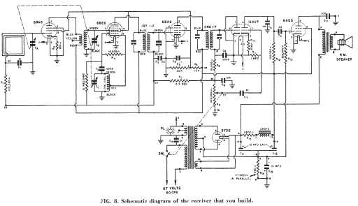
This National Radio Institute radio kit covers the AM broadcast band from 550 to 1700 KHz. The set was designed to be constructed as part of a radio course taught through NRI. Unlike some other correspondence course kits, it...