
National Radio Institute (NRI) AM radio kit
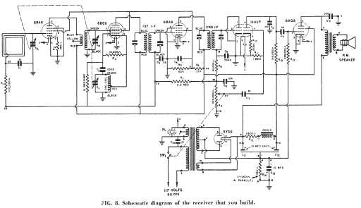
I was wondering if someone had substituted components or simply miswired a couple of items such as the power choke. It turns out that ALL of the unusual features were designed into the set. I obtained a paper copy from George K. of the 68 page NRI lesson set 7E1 for this radio titled "Practical Demonstrations of Radio-TV Fundamentals; Instructions for Experiments 61 to 70".
The unusual parts were either recycled from previous experiments or were included for a series of tests conducted in the process of building the radio. The tests and experiments include a simulated series of induced faults that are an excellent introduction to radio circuit faults and troubleshooting.
This set worked as obtained. Even though most of the capacitors in the set were in good condition and did not need replacement, I replaced several caps in critical circuits. Like many radios built from a kit, alignment was suspect. A quick check with a frequency counter showed that the IF was aligned at 436 KHz rather than the required 456 KHz.
Apparently the builder did not have a proper signal generator for alignment. The NRI lessons cover alignment without such a generator, but alignment mistakes are common in these sets. The pilot light is fixed into a grommet using a metal socket. To prevent short circuits in the event of grommet failure, I swapped connections on the pilot light so that the grounded side was connected to the exterior metal of the lamp socket.
The output transformer primary which carries the full B+ voltage is exposed at its solder terminals. I added heat shrink tubing since I prefer not to have exposed high voltage on the top side of a radio chassis. The power transformer appeared to be running a bit hot after about 45 minutes. Power draw was 0. 48 Amp. After checking voltages and specifications, I determined that the power draw was normal for the design.
However, I was not comfortable leaving it that way given present day power socket voltages. I added a choke for choke input and a 200 ohm resistor in the B+ circuit. This reduced the power draw to 0. 43 Amp, about a 10% reduction. The maximum B+ is now 309 volts, down from 345. The reduction had no effect on the radio other than reducing heat build-up. The NRI booklet notes that the radio, when properly constructed and aligned is equal in performance to better commercial sets. It is indeed. The tuned RF stage with a standard superhet set performs quite well at pulling in distant weak stations.
The le 🔗 External reference
Related Circuits
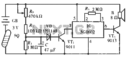
The circuit operates in such a way that when the patient is typically in an upright position, the SQ mercury switch is turned off, resulting in the alarm circuit being inactive. When the patient lies down, the SQ switch...
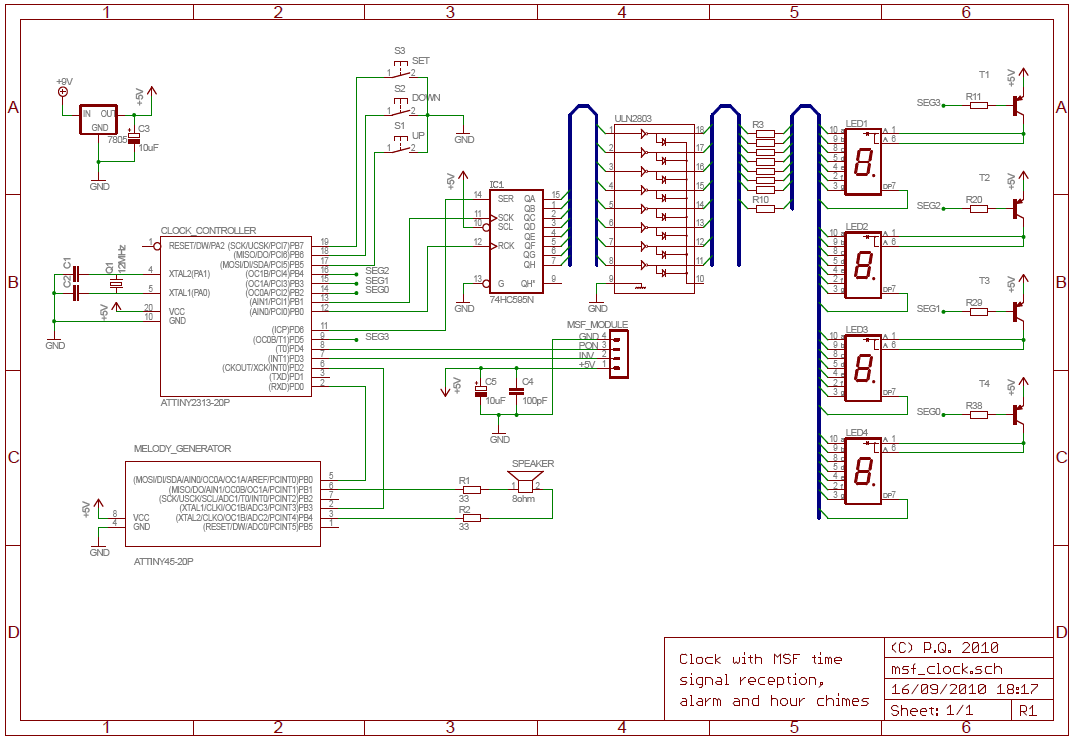
The National Physics Laboratory broadcasts a time signal, previously known as the Rugby clock but now called "Time from NPL." Its most commonly known as the MSF signal due to it originally being identified in Morse code those letters....
This is highly illegal. As a consumer, compliance with Part 15 of the rules and regulations is mandatory. Part 15 stipulates that a device must accept any interference it receives and must not cause harmful interference, such as jamming...
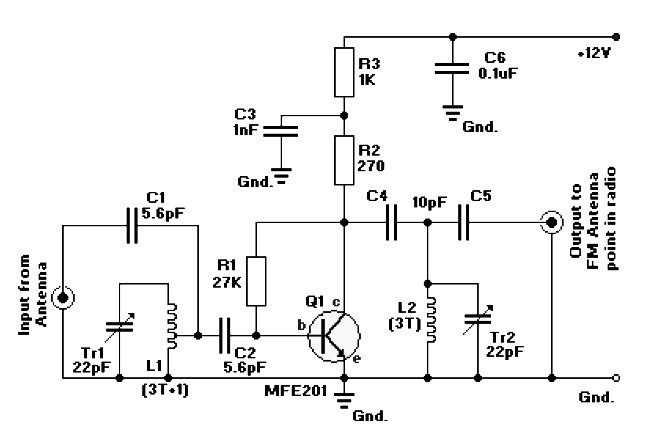
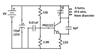
FM radio antenna amplifier circuit diagram. This amplifier will pull in all distant FM stations clearly. The active FM amplifier circuit is configured as a common-emitter tuned RF pre-amplifier wired around the VHF/UHF transistor MFE201. Below is a circuit...
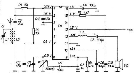
This AM radio receiver circuit utilizes the TDA1083 radio IC, which is suitable for constructing a simple medium frequency (MF) band radio. The schematic operates within a frequency range of 300 kHz to 3 MHz. The circuit is straightforward...
Ham Radio (amateur radio) is a popular hobby amongst electronics enthusiasts all over the world. Basically the hobby involves a person in making his own gear consisting of a receiver and transmitter or a transceiver (a receiver and a...