
morse Circuit
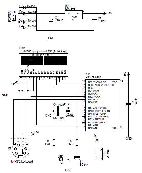
The described circuit utilizes a PIC microcontroller to interface with a PS/2 keyboard, allowing for the input of alphanumeric characters. The microcontroller processes the received data and translates each character into its corresponding Morse code representation. This conversion is achieved through a predefined mapping of characters to Morse code sequences, which consist of dots and dashes.
The output of the microcontroller is then used to generate an audio signal that represents the Morse code. This audio signal can be produced using a simple piezoelectric buzzer or speaker, which is driven by a PWM (Pulse Width Modulation) signal from the microcontroller. The duration of the audio signals is carefully timed to reflect the lengths of the Morse code symbols: short beeps for dots, longer beeps for dashes, and silence for the spaces between symbols and letters.
The circuit may include additional components such as pull-up resistors for the keyboard interface and capacitors for signal smoothing. Power supply considerations must also be addressed, ensuring that the microcontroller and audio output device operate within their specified voltage and current ratings. Overall, this circuit serves as a practical demonstration of interfacing digital input devices with audio output, showcasing the versatility of microcontroller applications in communication systems.This PIC-based hardware circuit accepts texts from a PS/2 keyboard and converts it into a morse code audio signal.. 🔗 External reference
Related Circuits
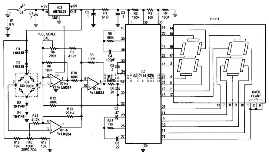
This circuit is designed to prevent further damage to old equipment that may be in unknown condition, particularly to devices that are already shorted. The circuit functions as a protective measure for vintage or malfunctioning electronic devices. It is particularly...
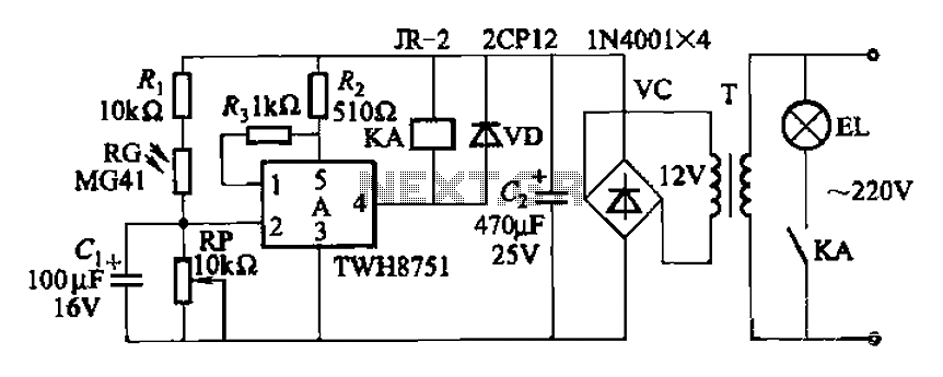
The adjustment potentiometer RP can modify the sensitivity of the device. Capacitors C1 function as an anti-light interference mechanism for instantaneous action. The adjustment potentiometer (RP) is a variable resistor that allows for fine-tuning of the device's sensitivity. By altering...
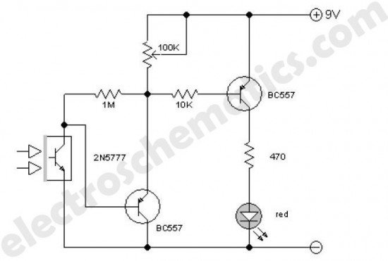
This enhanced infrared detector is designed for use with commercial infrared remote control handsets. This compact circuit is effective for quick go/no-go applications. The infrared detector circuit is engineered to respond to signals emitted by infrared remote control devices, commonly...

A circuit breaker is an automatically operated electrical switch designed to protect an electrical circuit from damage caused by overload or short circuit. Its basic function is to detect a fault condition and, by interrupting continuity, immediately discontinue electrical...
The BLW96 is a high-frequency (HF) and very high-frequency (VHF) power transistor designed for use in class A, AB, and B operated high-power industrial and military transmitting equipment. The BLW96 transistor is a crucial component in RF (radio frequency) applications,...
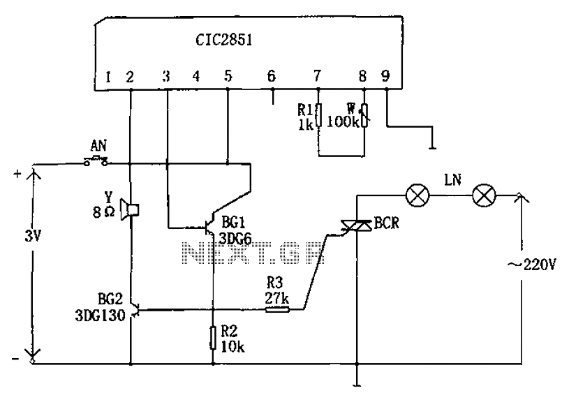
The non-contact lantern control circuit includes an integrated music IC (CIC2851), transistors (BG1 and BG2), a thyristor (SCR), and other components. When the switch is pressed (AN), the CIC2851 is activated, causing the output terminal (pin 3) to emit...