
Twelve road lighting control circuits
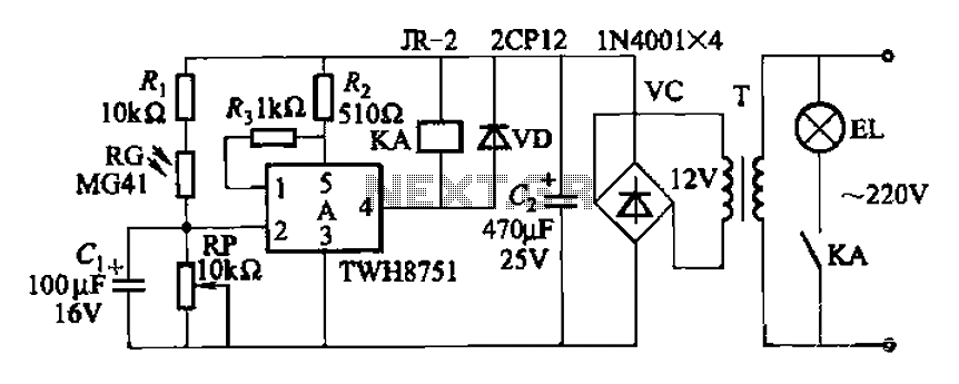
The adjustment potentiometer (RP) is a variable resistor that allows for fine-tuning of the device's sensitivity. By altering the resistance, the potentiometer can increase or decrease the responsiveness of the circuit to input signals, enabling the user to optimize performance based on specific requirements or environmental conditions. This feature is particularly useful in applications where precise control is necessary, such as in sensors or audio equipment.
Capacitor C1 serves a critical role in mitigating light-induced interference. It is designed to filter out high-frequency noise that can result from rapid changes in ambient light conditions. This anti-light interference capability is essential for maintaining the integrity of the device's operation, ensuring that it remains unaffected by transient light sources. The instantaneous action of the capacitor allows it to react quickly to fluctuations, providing a stable output signal that is less prone to distortion caused by external light interference.
In summary, the combination of the adjustment potentiometer and the anti-light interference capacitor creates a robust circuit that enhances the overall functionality of the device, allowing for adaptability in varying conditions while ensuring reliable performance.Adjustment potentiometer RP, can change the sensitivity of the device. Capacitors Cl as an anti-light interference of instantaneous action.
Related Circuits
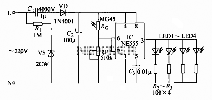
A 220V AC input is converted to a DC operating voltage of approximately 3.3V using a capacitive G buck regulator, a rectifier diode (VD), and a filter capacitor connected to an NE555 integrated circuit (IC). The IC functions as...
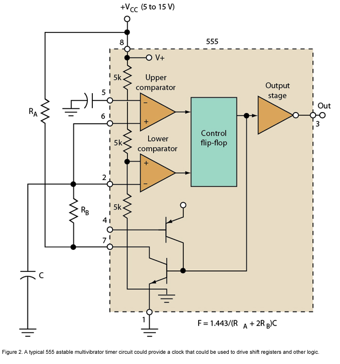
Micro or analog? These days, it is becoming increasingly challenging to make a choice. The 555 timer has long been regarded as a benchmark for flexibility. How does it perform today? The 555 timer IC, originally introduced in 1972, remains...
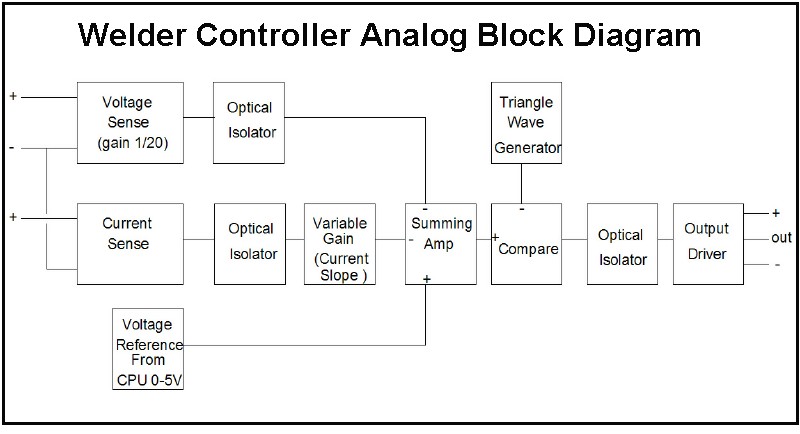
The first board is digitally controlled, while the actual welding current is analog. This design enables real-time operation without requiring the CPU to process the voltage or current. A block diagram illustrates its function: it operates as a switching...

This is an analog TV transmitter. Sound modulation is of the FM type with a 5.5 MHz carrier frequency, and video transmission follows the PAL standard. The frequency can be adjusted using capacitor C5, allowing tuning from 54 to...
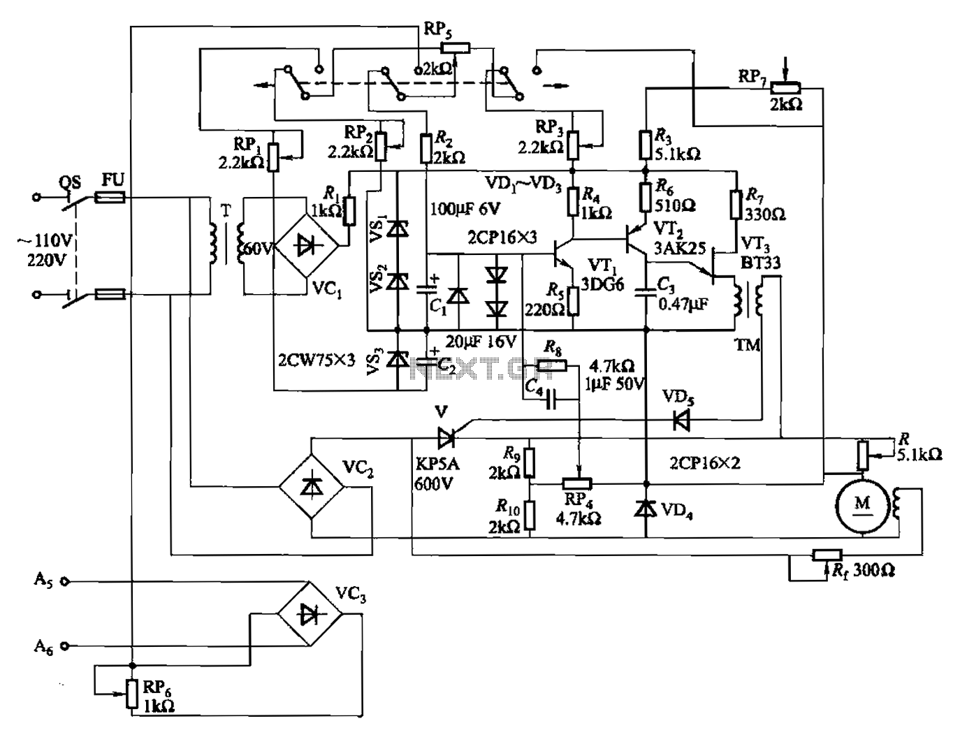
A 100W full-wave single-junction transistor trigger control circuit designed for constant or variable speed control of a wire feed motor. The input control signal consists of a voltage adjusted by the master potentiometer (RPs) and a feedback voltage from...

A dimming control circuit generates a dimming control signal to determine the brightness of at least one light-emitting diode. The dimming control signal consists of multiple bright-dark cycles, each comprising a bright phase and a dark phase. The bright...
Warning: include(partials/cookie-banner.php): Failed to open stream: Permission denied in /var/www/html/nextgr/view-circuit.php on line 713
Warning: include(): Failed opening 'partials/cookie-banner.php' for inclusion (include_path='.:/usr/share/php') in /var/www/html/nextgr/view-circuit.php on line 713