
mosfet 500 watt inverter with solar battery charger controller
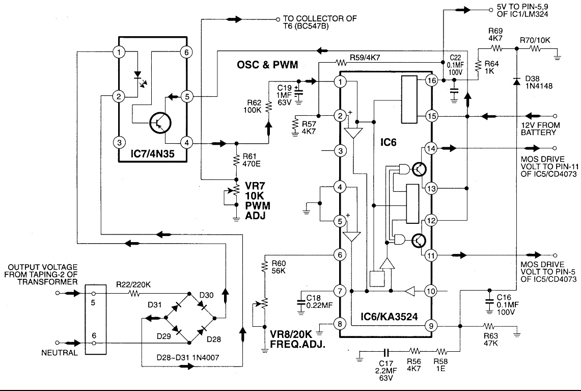
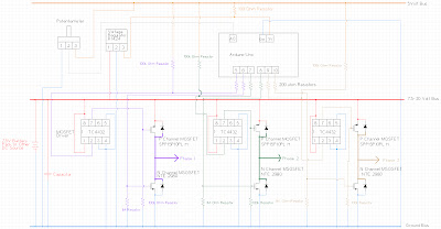
The inverter circuit comprises two primary sections: an oscillator circuit and a MOS driver circuit. The oscillator circuit is crucial for generating a high-frequency square wave signal, which serves as the control signal for the subsequent stages of the inverter. It operates on the principle of Pulse Width Modulation (PWM), where the duty cycle of the output signal can be adjusted to control the output voltage and power delivered to the load.
In the oscillator section, components such as resistors, capacitors, and operational amplifiers are configured to establish the desired oscillation frequency. The output of this section is a square wave that alternates between high and low states, which is essential for the operation of the inverter.
The second section, the MOS driver circuit, is responsible for amplifying the signals produced by the oscillator. It utilizes MOSFETs (Metal-Oxide-Semiconductor Field-Effect Transistors) to switch the output effectively. The driver circuit ensures that the MOSFETs are turned on and off at the correct times, allowing for efficient power conversion from DC to AC.
Together, these sections form a complete inverter circuit capable of converting a DC input into a usable AC output, making it suitable for various applications, including renewable energy systems, uninterruptible power supplies (UPS), and motor drives. The design emphasizes efficiency, reliability, and the ability to handle varying load conditions while maintaining stable operation.Circuit No. 1 (Oscillator Circuit and feedback circuit) Circuit No. 2 (MOS DRIVER CIRCUIT) FINAL PRODUCT: - WORKING OF THE CIRCUIT No.1 (Oscillator Circuit and feedback circuit) This Inverter is based on the Pulse Width Modulation technology. Working principle of various section of this INVERTER is explained next:- 1.Oscillator section:- This section generates the..
🔗 External reference
Related Circuits
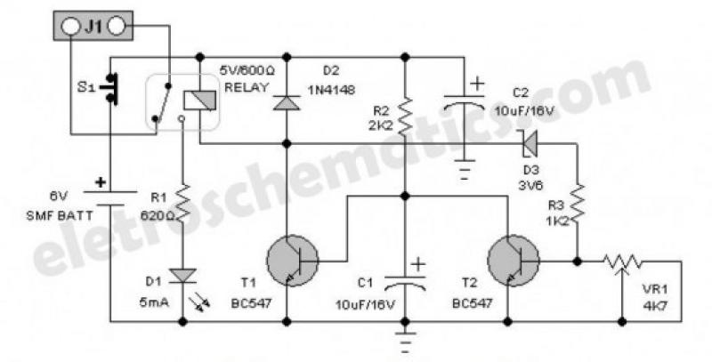
An emergency light is a light source designed to be available during emergencies. It operates automatically and is powered by a rechargeable battery. An emergency light system typically consists of several key components: a light source, a rechargeable battery, a...
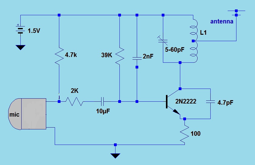
This simple FM (frequency modulation) transmitter is powered only by a 1.5V battery and utilizes a single transistor. The frequency of this transmitter is controlled by the L-C resonance circuit and operates within a range of 80 to 110...
This circuit is an automatic street light controller. The sensor used to detect changes in light is an LDR (Light Dependent Resistor). The working principle of the LDR is that when exposed to light, its resistance value decreases, while...
One of the primary objectives was to convert a generator into a motor using an Arduino. The process of transforming a simple generator into a motor proved to be particularly challenging with a three-phase generator, necessitating the creation of...
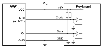
In many situations, a human interface is required for microcontroller projects. This example describes the interfacing of an AVR microcontroller with a standard PC AT keyboard. According to the keyboard timing diagram, the keyboard transfers data to the host...
Here is the schematic for an 8 watt audio amp. This amp can be used as a simple booster, the heart of a more complicated amplifier or used as a guitar amp. The circuit can be built on a...