
Three Phase 6 Pulse Inverter
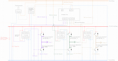
The circuit design for the three-phase inverter involves several key components that work together to convert DC power from the battery pack into a three-phase AC output suitable for driving a motor. The heart of the inverter consists of three pairs of transistors configured in a half-bridge arrangement. Each transistor pair is responsible for switching the current through the motor windings, creating the necessary phase shifts for three-phase operation.
The TC4432 MOSFET driver chips are crucial for driving the gates of the MOSFETs, ensuring that they switch on and off rapidly to minimize losses. It is vital to ensure that the MOSFET drivers are rated for the voltage levels being used; if the system operates above 30V, a more robust driver must be integrated into the design.
The resistors connected to the gate of the MOSFETs play a significant role in controlling the turn-on and turn-off characteristics, which affect the overall efficiency and performance of the inverter. A careful selection of resistor values is recommended to optimize switching times and prevent oscillations that could lead to MOSFET failure.
The voltage regulator (7805A R1424) is employed to provide a stable 5V supply to the Arduino for reliable operation. This regulator must be properly heat-sinked, especially when drawing significant current, to prevent thermal shutdown during operation.
The non-electrolytic capacitor serves to smooth out voltage ripples that can occur on the DC side of the inverter, ensuring a cleaner input signal to the switching circuitry. The selection of this capacitor should be based on its voltage rating and capacitance value to effectively filter noise without introducing significant lag in the response time.
Lastly, the battery pack configuration is critical for providing sufficient voltage and current to the inverter. The use of six rechargeable 1.25V batteries in series yields a nominal voltage of 7.5V, which is suitable for low-voltage applications. However, when using a higher voltage supply, careful attention must be paid to the connections and power supply to avoid damaging components or causing overheating.
In summary, the design of a three-phase inverter using an Arduino involves meticulous planning and component selection to ensure reliability and efficiency in converting DC power to three-phase AC power. Each component's role must be understood and integrated into the overall circuit to achieve successful operation.One of the primary things i wanted to do with my Arduino was turn my generators into motors. My simple generators were not simple to turn into motors but this proved to be particularly tricky with my three phase generator. Doing this requires me to create a three phase inverter. The first time I looked at a circuit for this, I thought it would be dead simple. All I need is a few transistors and a few diodes then I can hook them up like this: and it would work. This turned out to be untrue. That diagram really leaves out a whole lot of details which had me scratching my head for weeks. In particular the transistors connected to the high side just will not work without additional circuitry. 6- 200 ohm resistors (actually I ran out of these and used 100 ohm and 4000 ohm resistors from the output of the MOSFETs to the Arduino Uno, but 200 ohm are probably a better choice) 3- TC4432 MOSFET driver chip.
Be really careful with these, not sure if it was static on my part or poor quality control from the supplier but half of these didn`t work. If you want a inverter above 30V this component will need to be replaced with a different MOSFET driver.
Another alternative might be a charge pump circuit. 1- 7805A R1424 Voltage regulator. This powers the Arduino from the battery pack. The onboard voltage regulator on the arduino could probably substitute for this. 1- capacitor. Unfortunately this didn`t have a legible label on it so I am not quite sure what I used beyond that it was not an electrolytic capacitor so it was probably fairly low capacitance. This was just to lower any ripple which occurred on the DC side of the inverter. 1- battery pack with six rechargeable 1. 25 volt batteries. I also ran this circuit using a 20V DC supply but if you do this pin 3 on the TC4432s must be disconnected from ground and the voltage regulator must be replaced with a separate DC source to power the Arduino or the voltage regulator will overheat.
Above 30 Volts the circuit will need to be redesigned. 🔗 External reference
Related Circuits
The following circuit illustrates a Single Supply Phase Locked Loop Circuit Diagram. This circuit is based on the LM331 integrated circuit. Features include the response of... The Single Supply Phase Locked Loop (PLL) circuit utilizing the LM331 integrated circuit is...
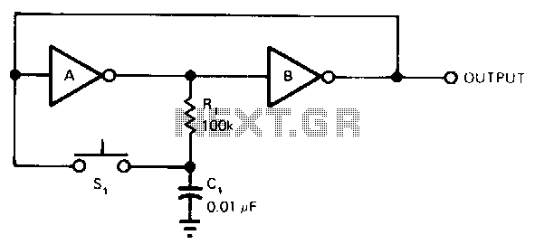
Each time the switch is closed, the voltage across capacitor C1 causes inverter A to change state, with positive feedback from inverter B. Resistor R1 delays the charging and discharging of C1, rendering the circuit nearly immune to contact...
A DC to AC inverter is utilized to convert a direct current (DC) voltage source into an alternating current (AC) voltage source. The operation of a DC to AC inverter circuit involves switching the DC voltage source to generate...
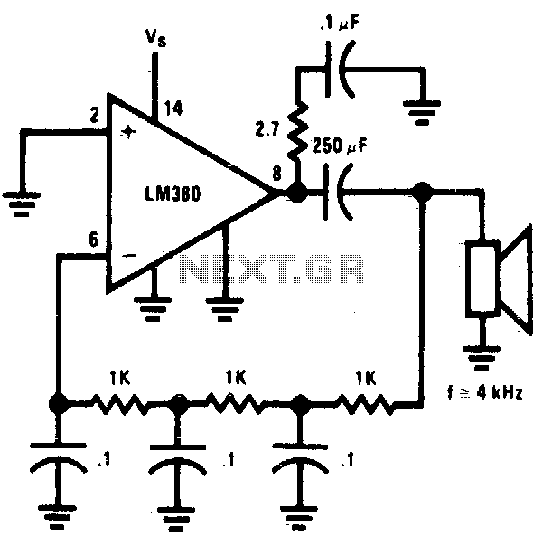
The circuit utilizes a simple RC network to generate a very high-pitched tone from a miniature speaker. With the specified component values, the circuit oscillates at a frequency of 3 kHz and drives a miniature 2W speaker at an...
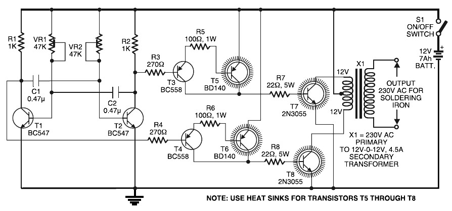
Simple Inverter for Soldering Iron. This is a straightforward and cost-effective inverter designed to operate small power soldering irons (25W, 35W, etc.) in the absence of mains supply. The circuit requires eight transistors along with several resistors and capacitors....
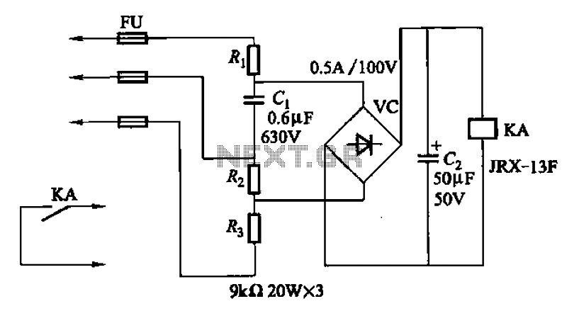
A capacitor C1 and resistors R1-R3 form a negative sequence voltage filtration device. The resistors and capacitors must meet the following requirements: R1, R2, R3 = 5.5/C1 (KN). The relationship between the resistance and capacitance values is arbitrary. Capacitor...
Warning: include(partials/cookie-banner.php): Failed to open stream: Permission denied in /var/www/html/nextgr/view-circuit.php on line 713
Warning: include(): Failed opening 'partials/cookie-banner.php' for inclusion (include_path='.:/usr/share/php') in /var/www/html/nextgr/view-circuit.php on line 713