
Interfacing PC keyboard to AVR microcontroller
The AVR microcontroller interfaces with the PC AT keyboard using a serial communication protocol that requires careful timing and data handling. The keyboard communicates with the microcontroller using a defined sequence of bits that must be accurately captured and processed. The start bit indicates the beginning of a transmission, while the stop bit signifies the end. The odd parity bit serves as a basic error-checking mechanism to ensure data integrity during transmission.
The keyboard's clock signal is crucial, as it dictates when data bits are sent and received. The microcontroller must synchronize its operations with this clock signal to correctly read the data line. The use of interrupts allows the microcontroller to respond to keyboard events in real-time, enabling a responsive user interface. When a key is pressed, the corresponding scan code is sent, and the microcontroller captures this code during the clock's falling edge, ensuring accurate data acquisition.
The algorithm's design allows for efficient handling of multiple key presses and releases, with break codes indicating when a key is no longer being pressed. The translation of scan codes to ASCII characters facilitates communication with other devices or systems via the RS232 interface. The implementation of a buffer to store received characters allows for the processing of input data before it is sent out, ensuring that the microcontroller can handle input without losing any information.
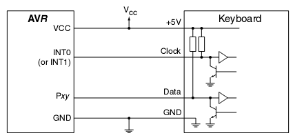
Overall, this setup provides a robust and flexible solution for interfacing a PC AT keyboard with an AVR microcontroller, enabling the development of various applications that require user input. The adaptability of the code to different AVR microcontrollers with SRAM further enhances its utility, allowing for a wide range of potential projects and applications in embedded systems.In many situations you need some kind of human interface to your microcontroller project. In this example is interfacing AVR microcontroller to standard PC AT keyboard described. According to keyboard timing diagram in bellow picture the keyboard transfers data to host AVR microcontroller. The protocol is: one start bit (always 0), eight data bits , one odd parity bit and one stop bit (always 1). The data is validated during the low period of clock pulse. Clock signal is generated by keyboard and pulses are about 30-50us low and high. The keyboard has a scan code associated with each key. When key is presse a‚ the code is transmitted. If key is is hol down for a while the code is transmitted repeatedly (about 10 times per s). After key is released the brake code is transmitted ($F0). Usually all keys have 8 bit length codes except some keys like Home, Insert and Delay have an extended codes from two to five bytes. The first bytes is always $E0. This is also true for the a‚ breaka‚ sequence e. g. E0 F0 xx The code in example is a simple keyboard to RS232 interface. Scanned codes are translated to ASCII characters and transmitted by UART. The code included in example can be adapted to any AVR microcontroller with SRAM. Algorithm is working in that way: Keyboard actions are handled by INT0 interrupt. The algorithm is quite simple: Store the value of the data line at the leading edge of the of the clock pulse.
Clock line is connected to one of interrupt pins (INT0 or INT1). The interrupt wil be executed every clock cycle. And data will be stored at the faling edge. After bits are received the data is decoded by decode function and characters are stored in a buffer. Other special keys (arrows, pagination keys, etc. ) are ignored. We aim to transmit more information by carrying articles. Please send us an E-mail to wanghuali@hqew. net within 15 days if we are involved in the problems of article content, copyright or other problems.
We will delete it soon. 🔗 External reference
Related Circuits
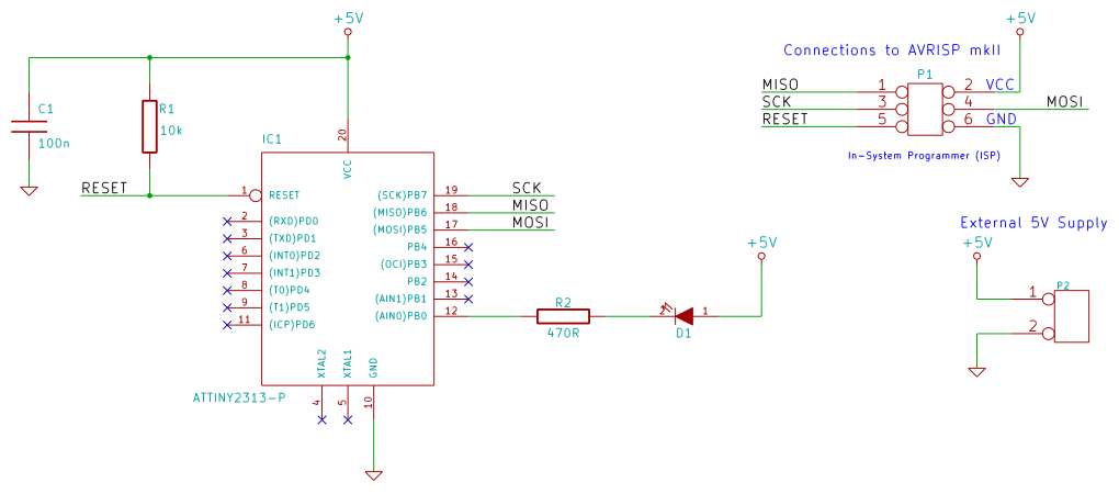
This tutorial examines the essential tools required for developing C programs on 8-bit AVR microcontrollers. It demonstrates how to write a C program and upload it to an AVR microcontroller, specifically utilizing an ATtiny2313 microcontroller breadboard circuit as a...
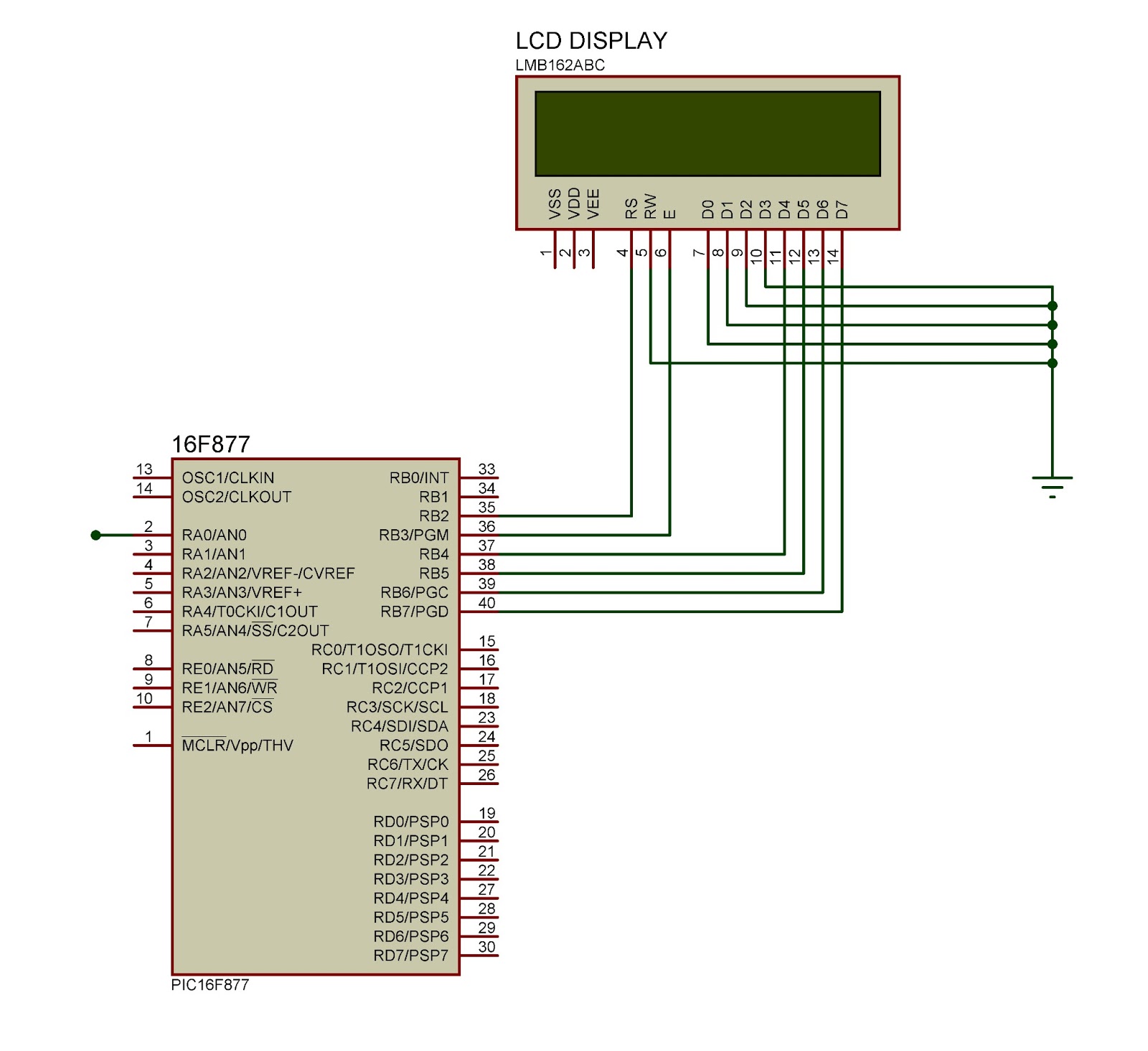
This document outlines the connection of a 16x2 LCD display to a microcontroller, specifically the PIC 16F877A. The circuit diagram is provided, although power supply and oscillator connections for both the PIC and LCD are not depicted. The LCD...
Many applications require a large number of keys connected to a computing system. Examples include PC keyboards, cell phone keypads, and calculators. Connecting a single key to a microcontroller unit (MCU) is straightforward; however, connecting 10 or 100 keys...
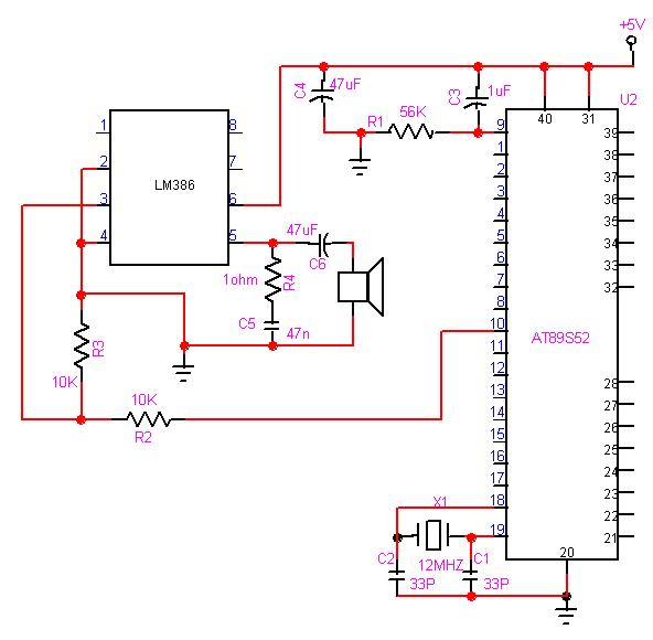
The 8051 microcontroller can play music tones. Here is a sample circuit and code that will play the music for "wishes you to be..." The 8051 microcontroller is a versatile and widely used microcontroller in embedded systems, capable of performing...

The filter consisting of resistors R1, R2, and capacitor C1 integrates the PWM waveform. The purpose of the operational amplifier appears to be that of a non-inverting amplifier, with the gain determined by resistors R6 and R7. However, the...
This project provides a simple temperature-controlled fan. If the difference between the actual temperature and the user-defined temperature is significant, the fan will operate. The temperature-controlled fan circuit utilizes a temperature sensor, a microcontroller, and a fan motor to regulate...