
MOSFET-based Joule Thief steps up voltage
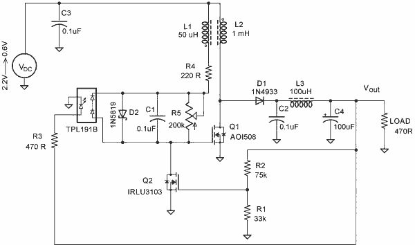
The blocking oscillator circuit is a type of oscillator that operates by inducing oscillations through positive feedback. It typically consists of a transistor, a coil (inductor), a capacitor, and a resistor. The fundamental operation relies on the rapid charging and discharging of the capacitor, which, in turn, influences the magnetic field in the inductor.
In this circuit, when the transistor is turned on, current begins to flow through the inductor, causing it to store energy in the form of a magnetic field. The inductor's property of resisting changes in current results in a gradual increase in current flow. Once the current reaches a certain threshold, the transistor enters saturation, and the magnetic field collapses rapidly. This sudden change in current induces a high voltage across the inductor, following the equation V = L di/dt.
The output voltage can be significantly higher than the input voltage due to this inductive kickback. The oscillation frequency of the circuit is determined by the values of the inductor and capacitor, as well as the characteristics of the transistor. The resistor serves to limit the current and stabilize the operation of the circuit.
The simplicity of the blocking oscillator circuit makes it suitable for various applications, including voltage converters, pulse generators, and signal modulation. It is important to ensure that the components are rated for the expected voltage and current levels to avoid damage and ensure reliable operation. Proper design considerations, such as component selection and layout, can enhance the performance and efficiency of the blocking oscillator circuit.A simple blocking oscillator circuit can be used to step up voltage using properties of coil inductance (V = L di/dt). Such a circuit is shown in Figure 1. 🔗 External reference
Related Circuits
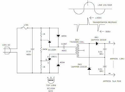
The hobby circuit described utilizes a unique method to generate approximately 12,000 volts with a current of about 5 microamperes. It employs two silicon-controlled rectifiers (SCRs) that form two pulse generator circuits. These SCRs discharge a 0.047 microfarad, 400-volt...
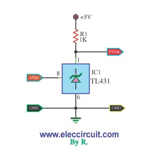
This is a simple pressure level check circuit, utilizing the integrated circuit TL431. It operates with a power supply of 5 volts for the digital circuit. The general feeding signal is... The circuit is designed to monitor pressure levels by...

This is a small circuit designed for use as a charging controller or voltage limiter. It is particularly useful for creating a solar charger. The assembly of the circuit allows for modifications according to personal preferences. The circuit is...
The SA9614 is an RF amplifier utilized for signal conversion and automatic laser power control (ALPC) between the CD optical pickup head and the decoding chip. The SA9614 incorporates an interface for the CD optical diode RF signal amplifier...
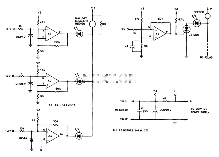
To maintain an alarm condition when an overvoltage transient disappears, an SCR should be added to the comparator circuits. For SCR operation, the voltages to the comparator inputs are inverted. The triple-voltage monitoring circuit detects transient power-supply over-voltages. If...
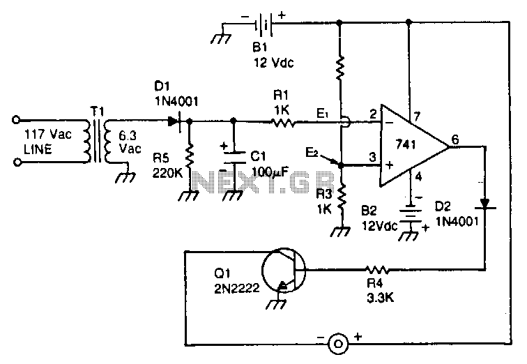
This circuit utilizes a type 741 operational amplifier (op amp) configured as a voltage comparator. One input of the 741 is connected to a reference voltage, sourced from a 12-V battery, via a resistor voltage divider. The voltage at...
Warning: include(partials/cookie-banner.php): Failed to open stream: Permission denied in /var/www/html/nextgr/view-circuit.php on line 713
Warning: include(): Failed opening 'partials/cookie-banner.php' for inclusion (include_path='.:/usr/share/php') in /var/www/html/nextgr/view-circuit.php on line 713