
MOSFET based step-up joule thief circuit

The circuit operates as a joule thief, which is a type of DC-DC converter designed to extract energy from a low-voltage power source, such as a single AA battery or depleted batteries. The low threshold MOSFET serves as the primary switching element, allowing it to turn on at lower voltages, making it suitable for maximizing energy extraction from the source.
The two coupled coils, typically configured as a transformer, play a crucial role in energy transfer. When the MOSFET is activated, current flows through one coil, generating a magnetic field. This magnetic field induces a voltage in the second coil, which can be significantly higher than the input voltage. The energy stored in the magnetic field is released when the MOSFET turns off, providing a boost in voltage to power the load.
The second MOSFET in the circuit functions as a regulator, ensuring that the output voltage remains stable despite variations in input voltage or load conditions. By controlling the duty cycle of the primary MOSFET, the regulator can adjust the energy transfer to the load, optimizing efficiency and preventing overvoltage conditions.
Overall, this circuit design is efficient for low-power applications, allowing for the utilization of energy from sources that would otherwise be considered unusable. It is commonly employed in applications such as LED drivers, low-power sensors, and other devices requiring energy harvesting from low-voltage sources.It uses a low threshold MOSFET and two coupled coils to operate as a joule thief. A second MOSFET is used to regulate the 🔗 External reference
Related Circuits
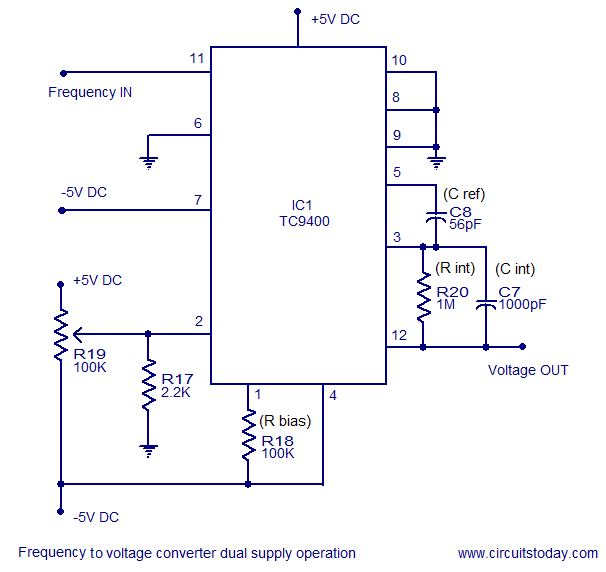
A simple frequency to voltage converter circuit designed around the TC9400 F to V / V to F converter IC. Dual and single supply versions are provided. The TC9400 is a versatile integrated circuit that converts frequency signals into corresponding...
The metal detector consists of a probe oscillator, a reference oscillator, an audio amplifier, and various other components, as illustrated in the schematic. The probe oscillator is made up of transistors V1 and V2, a detection coil L1, a...
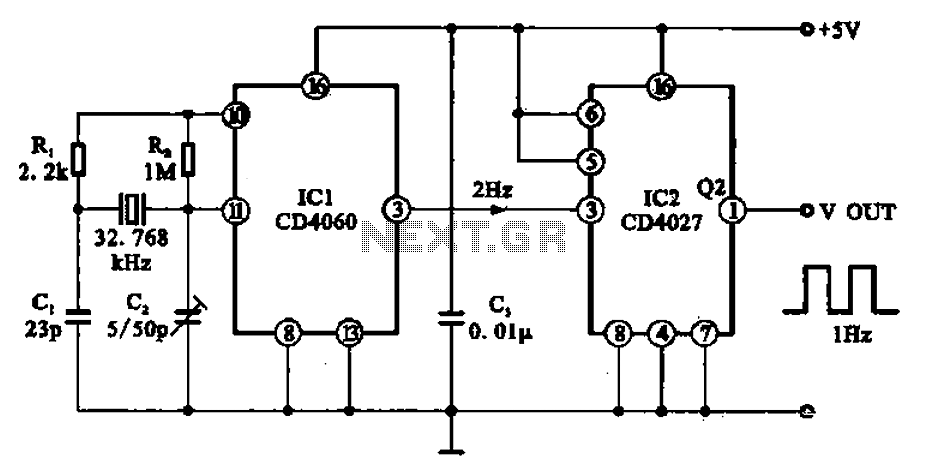
A 1Hz clock signal generator circuit is presented, which demonstrates a sophisticated clock signal generating mechanism. This circuit can be utilized for digital clocks and timing applications. It comprises a binary counter (CD4060), a JK flip-flop (CD4027), and a...
This circuit is a wireless car alarm system composed of two modules: a transmitter and a receiver. It operates using FM radio waves and is compatible with vehicles that have a 6-12V DC power supply. If the vehicle's power...
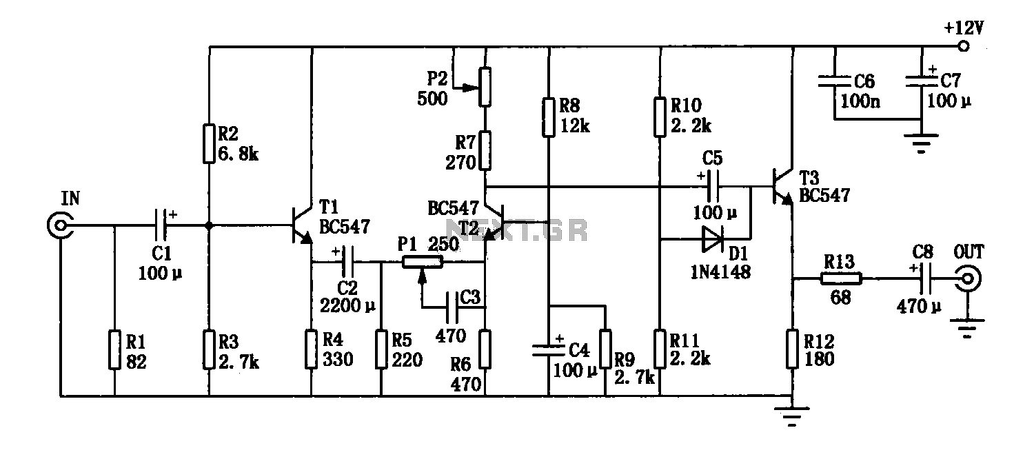
The enhancement circuit, as depicted, increases the high-frequency components of the video signal, thereby improving the contrast of the television image. It can be connected between the VCR and the TV SCART input. The circuit utilizes transistor T1 for...
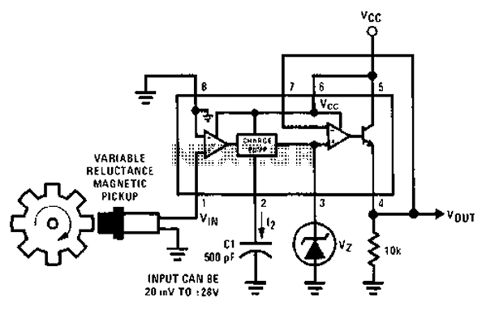
After each zero electromagnetic pickup receives a sine wave input, as illustrated in the National Semiconductor LM2907 circuit, it generates an output pulse. This circuit can be utilized in digital control systems. The width of each pulse corresponds to...