
1Hz clock signal generator circuit
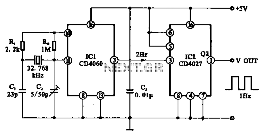
The 1Hz clock signal generator circuit operates by leveraging the properties of a binary counter and a JK flip-flop. The CD4060 binary counter is primarily responsible for frequency division. It begins with the input frequency from the 32.768 kHz quartz crystal, which is a standard frequency used in timekeeping devices due to its accuracy and stability. The counter divides this frequency down through a series of flip-flops, achieving the necessary output frequency.
The JK flip-flop (CD4027) serves as an additional stage to further refine the output signal. It is configured to toggle its output state with each clock pulse received, effectively halving the frequency of the signal from the binary counter. The use of a tuning capacitor allows for fine adjustments to the oscillator frequency, ensuring the output remains stable and accurate, which is crucial for applications requiring precise timing.
The final output of the circuit, which is a 1 Hz square wave, is suitable for driving digital clock displays or other timing circuits. This output can be interfaced with additional circuitry for display purposes or other timing-related functions. The design emphasizes reliability and precision, making it an ideal choice for both hobbyist projects and more advanced electronic applications. The integration of the CD4060 and CD4027 components in this configuration provides a robust solution for generating a stable clock signal necessary for various electronic devices.1Hz clock signal generator circuit It shows a sophisticated l llz clock signal generating circuit. Can be used for digital clock and timing circuits: The circuit consists of 14 binary counter CD4060, JK flip-flop CD4027 and 32.768 kHZ quartz crystal device components. IC1 ?, pin external crystal body and the circuit chip oscillator circuit, the oscillation frequency of 32.768 kHz, tuning capacitor Q can be precisely adjusted to this frequency. The oscillation signal by ICI by 21. After the second division, the output of IC1 2 Hz square foot is a signal, the signal through the IC2 party boat after 1,2 division, will come out in IC2 cuckoo O pin output frequency is accurate clock 1} Mu signal.
-
Related Circuits
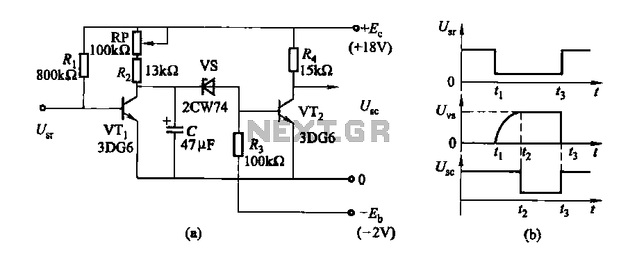
The delay time ranges from 0.5 to 3.5 seconds, which can be adjusted using the potentiometer RP to modify the delay duration. The circuit utilizes a timing mechanism that allows for the adjustment of delay intervals between 0.5 seconds and...
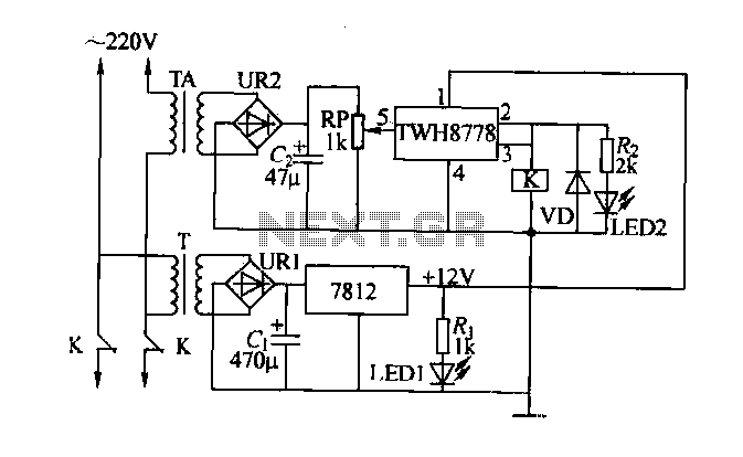
An electric power limiter circuit restricts the user load, ensuring that household appliances operate within a specified normal current range. When the load exceeds a predetermined threshold, the power supply is disconnected. This circuit utilizes the high-power integrated TWH8778...
Incorporate resistors in a parallel configuration to enhance audio input. To control the volume for each input channel, integrate a linear trimmer or potentiometer with the following configuration: pin 1 connects to ground, pin 2 serves as the output,...
Delay electronic doorbell circuit - touch doorbell amplifier circuit The delay electronic doorbell circuit is designed to provide a user-friendly interface for doorbell activation, utilizing a touch-sensitive amplifier circuit. This circuit typically incorporates a touch sensor that detects user interaction,...
This is a 1-watt FM amplifier with an effective design that can be used to amplify an RF signal in the 88 - 108 MHz band. It exhibits high sensitivity when paired with quality RF components. The 1-watt FM amplifier...
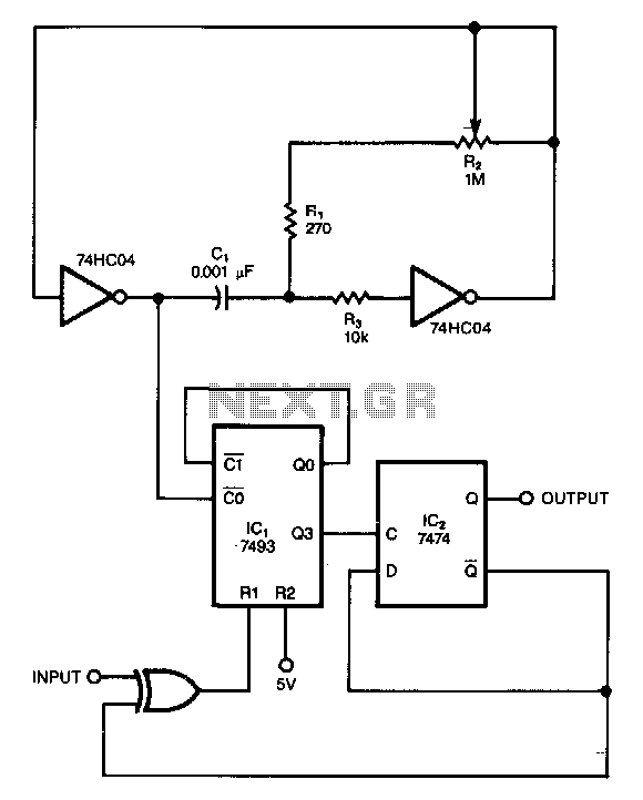
This circuit filters noise, such as glitches and contact bounce, from digital signals. It can be easily adjusted for a wide range of noise frequencies. The circuit's output changes state only if the input differs from the output long...