
Tachometer circuit diagram of a multiplier
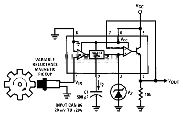
The National Semiconductor LM2907 is a versatile frequency-to-voltage converter that can be effectively employed in various digital control systems. When a sine wave input is applied to the zero electromagnetic pickup, the LM2907 processes this signal to produce a corresponding output pulse. The frequency of the input signal determines the pulse width, which is directly influenced by the capacitance value of capacitor C1 in the circuit.
In practical applications, the output pulse width can be adjusted by varying the capacitance of C1, allowing for fine-tuning of the circuit's response to different input frequencies. The power supply voltage applied to the circuit is also critical, as it affects the overall performance and stability of the LM2907. A stable power supply ensures that the output pulse remains consistent, which is essential for reliable operation in digital control systems.
Furthermore, this circuit serves as a multiplier for microprocessor control systems, enabling the integration of analog signals into digital processing environments. By converting the frequency of the input sine wave into a pulse width that can be read by a microprocessor, it allows for the implementation of complex control algorithms and feedback systems. This capability is particularly useful in applications such as motor control, signal processing, and automated systems where precise timing and control are required.
Overall, the LM2907 circuit's ability to generate output pulses based on sine wave inputs makes it a valuable component for engineers designing advanced electronic control systems.After each zero electromagnetic pickup has a sine wave input, as shown in the National Semiconductor LM2907 circuit will produce an output pulse, the circuit can be used for di gital control system in. Width of each pulse is a C1 size and the power supply voltage used in the decision. Circuit is a multiplier for the microprocessor control system services.
Related Circuits
This inverter is designed to operate appliances such as TVs and stereos while traveling or camping. It converts 12 VDC to 120 VAC, with the output wattage determined by the transistors used for Q1 and Q2, as well as...

A simple infrared-controlled switch can be operated using a TV remote control. The load can be any AC-powered device connected to the relay. The load activates for three minutes before turning off and can be used to switch on...
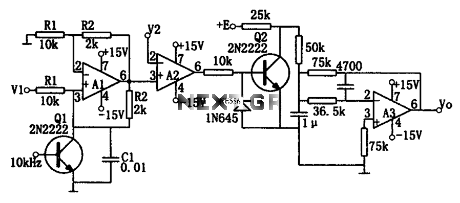
As illustrated in the dividing circuit diagram, A1 consists of a voltage-controlled current source, A2 functions as a voltage comparator, and A3 is configured as an active low-pass filter. When the time constant R1C1 is equal to the clock...
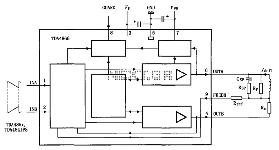
The TDA4866 is a 90-color power amplifier designed for vertical deflection systems, operating at a frequency range of 50 to 160 Hz. The CRMM circuit is implemented to ensure a high current drive input. The amplifier features a dual...
The main circuit of the 6-channel mixer consists of six input channels. Channels 1-4 are mono, while channels 5-6 are designed for music use. The number of input channels can be increased as desired. The output of each channel...
The circuit diagram of an IC Controlled Emergency Light with Charger, also known as a 12V to 220V AC inverter circuit, is presented here. This circuit features automatic activation of the light during mains failure and includes a battery...