
MOSFET Headphone amplifier

The volume control, Rp, is optional, because the driver is meant to be fed from a source with a volume control. If the volume control is not used, then it would be a good idea to put a discharging resistor in front of the input coupling capacitor C1 to ground - around 100K ohms. Sometimes the preamp is capacitor outputted, but may not have a discharging resistor. So, in the worst case, there would be capacitors back to back, and the voltage bias in between the capacitors would not be necessarily predictable (e.g., at or near zero volts to ground), or could cause some pops when connecting with the power on. A volume control accomplishes the same thing with its resistance to ground.
All capacitors should be the highest quality, especially the output capacitor. The output capacitor is an easier-to-get size capacitor of 470 microFarads, but one could at least double that for better low response. Bypass it with a quality 1 microFarad polypropylene cap for the best sound. I included the discharge resistor R5 to help eliminate pops when inserting the headphone plug. The input resistor would do the same if the input was inserted live. It might also help eliminate turn-on thumps.
The MOSFET (Q1) should be mounted on a heat sink. Almost any heatsink could be used. Q1 dissipates up to 2.5 watts. I think about 2-3 square inches surface area is minimum, and probably should be more. I just mounted them to the chassis with insulators in my model. A LITTLE silicone grease is nice. The MOSFET and R4 will get warm during operation, which is normal. With R4 = 20 ohms, the source resistors and MOSFETS will dissipate up to 7 watts in the stereo pair using a 15 volt supply. R4 could be changed to even lower values - its simply a matter of delivering enough current out of the supply and providing enough heat dissipation.
The IRF513 is an N-channel power MOSFET, rated at V(ds) = 80V, I(d) = 4.9A and r(ds) = 0.74 ohms. I chose a device with a reasonably small resistance. A higher resistance, lower-rated device could also be used. There is a large selection from which to choose. Q1 draws less than 200 ma. at 9 volts. One thing I didn't try was to use two circuits per side, so one could use direct coupling on the output side by feeding the signal to one side, and using the other side to provide a positive but equal resting voltage creating an effective zero-DC operating point. I wanted something simple though.
The described circuit is a MOSFET follower designed to drive headphones, leveraging the characteristics of Field Effect Transistors (FETs) which can provide high output current while maintaining a voltage gain slightly below unity. This makes the circuit ideal for interfacing with low-level signals from devices such as preamplifiers or portable audio sources where amplification is not required.
The circuit requires a regulated power supply and includes input and output capacitors, ensuring stable performance. The use of a potentiometer instead of fixed resistors for biasing allows for adjustable output levels, optimizing the MOSFET's output potential. Resistor R1 serves as a current limiter to protect the circuit from excessive input current. Additionally, the inclusion of reversed-biased diodes provides over-voltage protection, effectively clamping any spikes above 9 volts or below -1 volt, although the circuit can operate without these diodes.
An optional volume control (Rp) can be added; however, if omitted, a discharging resistor (around 100K ohms) should be connected to ground to prevent unpredictable voltage biases between capacitors, which can lead to unwanted noise when powering on. The circuit design emphasizes the use of high-quality capacitors, particularly for the output stage, where a 470 microFarad capacitor is recommended, potentially increased for enhanced low-frequency response. A bypass capacitor of 1 microFarad, preferably polypropylene, is suggested to improve audio fidelity.
To mitigate pops when connecting headphones, a discharge resistor (R5) is included, and a similar function is provided by the input resistor during live connections. The MOSFET (Q1) must be mounted on a heatsink due to the heat generated during operation, with a recommended surface area of 2-3 square inches to adequately dissipate the heat. The selected IRF513 MOSFET has a voltage rating of 80V and a current rating of 4.9A, with a low on-resistance of 0.74 ohms, ensuring efficient operation. The circuit is designed to draw minimal current (less than 200 mA at 9 volts), and while the possibility of using multiple circuits for direct coupling was considered, the simplicity of the design was prioritized.The circuit described in this article is a MOSFET follower for driving headphones. FET followers can supply high current, but have a voltage gain of slightly less than unity. They are most suitable in applications where the input signal does not require voltage amplification - such as the output of a preamplifier or a portable stereo. If the input signal is too low, you can add voltage gain stage . The class A headphone driver in figure 1 is ultra simple, except it does need a regulated supply and input and output capacitors. Most of the parts are not critical. I used a pot instead of the 100K bias resistors, so I could vary the output side of the MOSFET at 1/2 the supply.
This maximizes the ouput potential of this driver. R1 limits the input current. The diodes are reversed-biased protection only. They short out spikes greater than 9 volts and negative 1 volt. In the original I used a 9 volt zener diode instead, but I figured it's harder to get zeners. The circuit will work without the diodes. The volume control, Rp, is optional, because the driver is meant to be fed from a source with a volume control. If the volume control is not used, then it would be a good idea to put a discharging resistor in front of the input coupling capacitor C1 to ground - around 100K ohms.
Sometimes the preamp is capacitor outputted, but may not have a discharging resistor. So, in the worst case, there would be capacitors back to back, and the voltage bias in between the capacitors would not be necessarily predictable (e.g., at or near zero volts to ground), or could cause some pops when connecting with the power on. A volume control accomplishes the same thing with its resistance to ground. All capacitors should be the highest quality, especially the output capacitor. The output capacitor is an easier-to-get size capacitor of 470 microFarads, but one could at least double that for better low response.
Bypass it with a quality 1 microFarad polypropylene cap for the best sound. I included the discharge resistor R5 to help eliminate pops when inserting the headphone plug. The input resistor would do the same if the input was inserted live. It might also help eliminate turn-on thumps. The MOSFET (Q1) should be mounted on a heat sink. Almost any heatsink could be used. Q1 dissipates up to 2.5 watts. I think about 2-3 square inches surface area is minimum, and probably should be more. I just mounted them to the chassis with insulators in my model. A LITTLE silicone grease is nice. The MOSFET and R4 will get warm during operation, which is normal. With R4 = 20 ohms, the source resistors and MOSFETS will dissipate up to 7 watts in the stereo pair using a 15 volt supply. R4 could be changed to even lower values - its simply a matter of delivering enough current out of the supply and providing enough heat dissipation.
The IRF513 is an N-channel power MOSFET, rated at V(ds) = 80V, I(d) = 4.9A and r(ds) = 0.74 ohms. I chose a device with a reasonably small resistance. A higher resistance, lower-rated device could also be used. There is a large selection from which to choose. Q1 draws less than 200 ma. at 9 volts. One thing I didn't try was to use two circuits per side, so one could use direct coupling on the output side by feeding the signal to one side, and using the other side to provide a positive but equal resting voltage creating an effective zero-DC operating point. I wanted something simple though. 🔗 External reference
Related Circuits
This circuit is designed for use with inductive pick-up elements and dynamic microphones. Most soundcards feature a line input and a dedicated input for electret (condenser) microphones. To connect an inductive tape recorder head or a dynamic microphone, an...
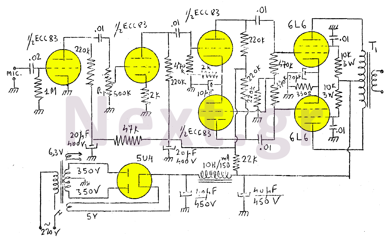
The amplifier in this design is rated at 30 Watts and is intended for use with a microphone. It is compatible with a crystal microphone and can be utilized for speeches, lectures, as a transmitter modulator, and in applications...
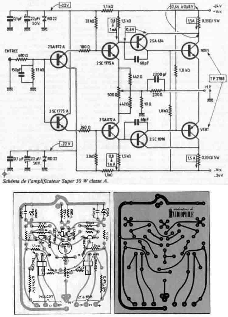
I used the original board layout shown in the magazine article as well as the original driver transistors. However, due to the unavailability of the original power transistors, I opted for a more robust output stage using Toshiba 2SA1943...
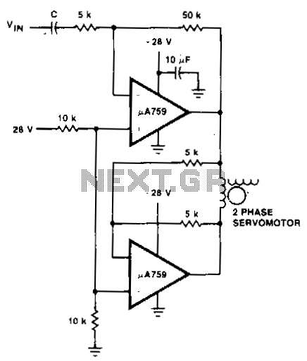
This motor driver circuit utilizes a p.A759 power amplifier to drive a two-phase servomotor. The motor driver circuit is designed to efficiently control a two-phase servomotor, leveraging the capabilities of the p.A759 power amplifier. This amplifier is specifically chosen for...
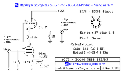
This is one of many available variations for a Symmetrical SRPP Preamplifier based on the 6DJ8 / ECC88 family of tubes. The SRPP circuit has also been referred to as a SEPP, Totem Pole, Mu Follower, Mu amplifier, and...
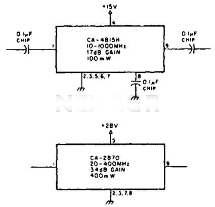
Using TRW part number CA-815H, a 17 dB gain amplifier capable of delivering 100 mW over a frequency range of 10 to 1000 MHz can be constructed. Additionally, the CA-2870 can provide 0.4 W with a gain of 34...