
Wideband Power Amplifier Circuit
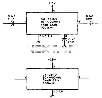
The TRW CA-815H is a high-performance amplifier designed for applications requiring moderate gain and wide frequency response. With a gain of 17 dB, it is suitable for use in various RF applications, such as communication systems, signal processing, and instrumentation. The amplifier operates efficiently across a broad frequency range of 10 to 1000 MHz, making it versatile for both narrowband and wideband applications. The output power of 100 mW allows it to drive moderate loads effectively, ensuring signal integrity in transmission lines.
In contrast, the CA-2870 amplifier offers significantly higher performance for specific applications, providing a gain of 34 dB and an output power of 0.4 W. This amplifier is optimized for frequencies between 20 and 400 MHz, making it ideal for applications such as television broadcasting, FM radio, and other communication systems that operate within this frequency range. The increased gain and output power of the CA-2870 allow for improved signal amplification, which is crucial in scenarios where signal strength is critical for maintaining communication quality.
Both amplifiers can be integrated into various circuit designs, including cascaded amplifier configurations and signal conditioning circuits. Proper impedance matching and power supply considerations are essential for maximizing performance and minimizing distortion. Additionally, thermal management techniques should be employed to ensure reliable operation, especially in high-power applications. The selection between the CA-815H and CA-2870 will depend on specific application requirements, including frequency range, gain, and output power needs. Using TRW P/N CA-815H, a 17-dB gain amplifier that delivers 100 mW over 10 to 1000 MHz can be constructed. The CA-2870 will yield 0.4 W with 34-dB gain from 20 to 400 MHz. 🔗 External reference
Related Circuits
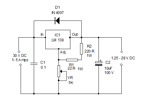
High Current Variable Power Supply Circuit Diagram. The widely used variable voltage regulator IC LM317 can handle a maximum current of only 1 ampere, making it unsuitable for applications requiring a high current variable power supply. The design of a...

This circuit combines two or more audio channels into a single channel (for example, converting stereo to mono). It is capable of mixing multiple channels while consuming minimal power. The schematic illustrates two inputs, but additional inputs can be...
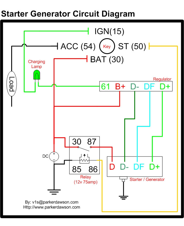
Circuit diagrams for both a Bosch and a Delco-Remy Starter-Generator are available, noting that the circuits differ. Due to a computer crash, the original diagrams and the associated email address were lost. However, in May 2004, both the email...
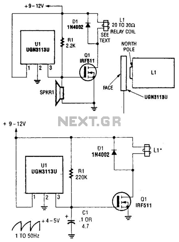
Although not intended for this application, a Hall-effect switch can be utilized as the foundation for an unconventional oscillator. The oscillator can be reconfigured, as illustrated in Fig. B, to enable the circuit's oscillating frequency to be regulated through...

A compact, inexpensive and low component count telecom headset can be constructed using two readily available transistors and a few other electronic components. This circuit is very useful for hands-free operation of EPABX and pager communication. Since the circuit...
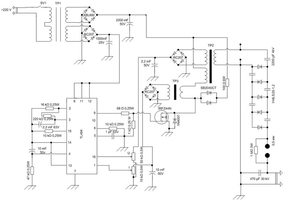
The schematic diagram is derived from the circuit of a High Voltage Power Supply utilizing the PWM IC TL494. This power supply requires a suitable alternating voltage source of 12 V / 800 mA. An alternating voltage is rectified...
Warning: include(partials/cookie-banner.php): Failed to open stream: Permission denied in /var/www/html/nextgr/view-circuit.php on line 713
Warning: include(): Failed opening 'partials/cookie-banner.php' for inclusion (include_path='.:/usr/share/php') in /var/www/html/nextgr/view-circuit.php on line 713