
Mosfet Heating Circuits
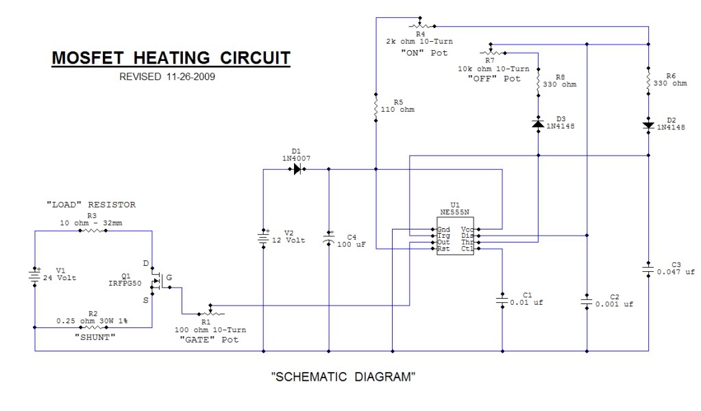
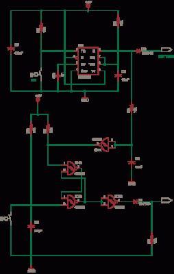
The MOSFET Heating Circuit is designed to efficiently manage and control heating elements using MOSFET technology. MOSFETs (Metal-Oxide-Semiconductor Field-Effect Transistors) are preferred in heating applications due to their high efficiency and fast switching capabilities. The circuit typically consists of a power supply, a MOSFET, a microcontroller or control circuit, and the heating element itself.
In this schematic, the power supply provides the necessary voltage to the circuit, which is often in the range of 12V to 24V, depending on the heating element specifications. The MOSFET acts as a switch, controlling the flow of current to the heating element based on the input signal from the microcontroller. The microcontroller can be programmed to adjust the duty cycle of the PWM (Pulse Width Modulation) signal, allowing for precise temperature control.
Additional components may include resistors for gate drive circuitry, capacitors for filtering, and diodes for flyback protection if inductive loads are used. A heat sink may be necessary for the MOSFET to dissipate heat generated during operation, ensuring reliable performance.
Safety features such as thermal cutoffs or fuses can be integrated into the design to prevent overheating and potential damage to the circuit. Overall, this MOSFET Heating Circuit represents an effective solution for applications requiring controlled heating, such as in 3D printers, soldering tools, or temperature-sensitive processes.This Open Source thread is for the advancement of a ""Mosfet Heating Circuit"" one that is a modified replication of one.. 🔗 External reference
Related Circuits
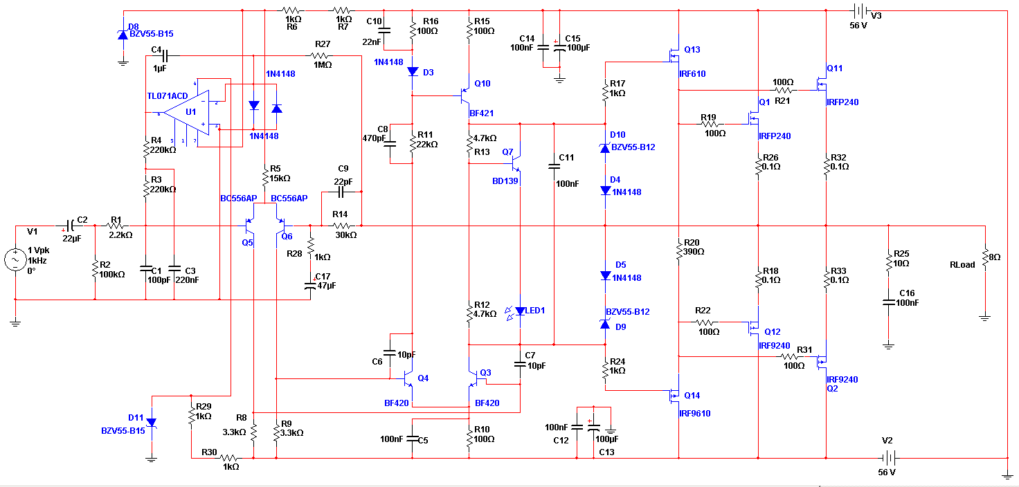
The Apex amplifier has a corrected schematic that includes variations of the resistor R14 with different values (22k, 30k, 56k) and different power supply configurations. The Apex amplifier circuit is designed to deliver high-fidelity audio amplification. The schematic incorporates a...
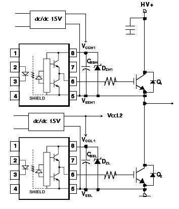
An H-bridge circuit has been developed utilizing four floating gate drivers and four insulated gate bipolar transistors (IGBTs). The attached schematic illustrates one half of the H-bridge configuration. The circuit operates effectively, but there are additional considerations to address. The...
The circuit presented is a standard Colpitts oscillator, commonly utilized in many amateur radio homebrew transmitters. This specific circuit is designed to operate effectively within a frequency range of 1500 kHz to 8000 kHz. To accommodate lower frequencies, it...
This circuit is a simple -5V power supply using a 555 timer, designed for low-power analog applications involving FET operational amplifiers. The circuit converts +5V to -5V to create a dual power supply. It operates as a 555 astable...
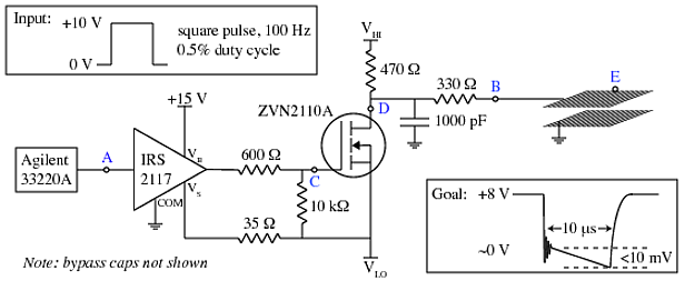
A copper mesh measuring 10 cm x 10 cm is situated in a vacuum chamber and connected to a BNC connector via a 24 cm copper wire. The objective is to rapidly switch the voltage across the mesh (referenced...
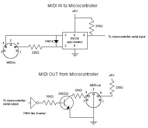
MIDI, or Musical Instrument Digital Interface, is a specification for a communications protocol between digital synthesizers and other digital music devices. It was developed to be as simple and general as possible, providing synthesizer manufacturers with significant flexibility while...