
crystal oscillator circuits
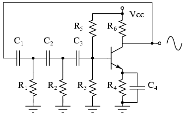
The Colpitts oscillator circuit is characterized by its use of two capacitors (C1 and C2) and an inductor (L) to create an LC tank circuit that determines the oscillation frequency. The feedback mechanism is accomplished through a combination of the capacitors and the transistor (Q1), which amplifies the signal. The frequency of oscillation can be calculated using the formula:
\[ f = \frac{1}{2\pi\sqrt{L \cdot C_{total}}} \]
where \( C_{total} = C1 \cdot C2 / (C1 + C2) + C_{stray} \). The stray capacitance, often present in the circuit, should also be considered in practical applications.
The variable capacitor in the enhanced version allows for fine-tuning of the oscillation frequency, making it adaptable for different applications. The buffer amplifier (Q2) serves to isolate the oscillator from the load, preventing any loading effects that could destabilize the oscillation.
The addition of harmonic suppression and output matching stages in the AM transmitter configuration is crucial for ensuring that the transmitted signal meets regulatory standards and minimizes interference with other communication channels. The final output stage must be designed to match the impedance of the antenna for optimal power transfer, typically 50 ohms for most radio applications.
Overall, the Colpitts oscillator is a versatile and fundamental circuit in the field of radio frequency (RF) engineering, suitable for various applications ranging from simple transmitters to more complex RF systems.The circuit below is a standard oscillator of the Colpitts variety. Similar circuits have been used in many ham radio homebrew transmitters. This particular circuit should function well at frequencies from 1500 kHz to 8000 kHz. For use on lower frequencies, the values of C1 and C2 might need to be increased. If you`ve never built a circuit from a schematic before, this might be a good one to start with. The diagram below shows how you can arrange the parts on a prototyping board such as Radio Shack catalog number 276-175. (A prototyping board, also called a solderless breadboard, contains groups of holes that are electrically connected.
Each hole has a little spring/clamp thingy in it that grabs ahold of the component leads. This is a great way to experiment with circuit designs and learn about the building process. ) Attach a 10-inch (25 cm) piece of bare wire to the output, then sit a radio next to the circuit and tune to the crystal frequency. Apply power. If everything is connected correctly and all the components are in working order, you will hear the carrier (or the silence caused by it) on your receiver.
Now all you need to do is add a buffer amp, a modulation stage, a final RF amp, a harmonic suppression and output matching section, and you`ve got an AM transmitter. :-) Below is another version of the circuit with a couple of enhancements. The variable capacitor between the crystal and ground allows you to adjust the frequency slightly. (More capacitance equals lower frequency. ) Q2 serves as a buffer amplifier which stabilizes the circuit and boosts the output power. This circuit was developed independently by another MWA member and uses very different values for R1, C1 and C2 compared to the first circuit on this page; don`t let those differences scare you.
Another common variation of the Colpitts circuit involves adding a resistor parallel to the crystal, as shown below. What`s the advantage I have no idea. The circuit shown has been tested and works fine at frequencies from 1. 5 to 20 MHz. To round out the collection, here`s a Pierce oscillator using an FET. The version on the left is from an electronics textbook. The version on the right is from the "Grenade" shortwave pirate radio transmitter designed by "Radio Animal.
" Some people might prefer an oscillator that uses a crystal at 4 times the operating frequency and then divides by four to produce the carrier wave. Advantages are 1) your signal will have a super stable frequency with immeasurably low drift, and 2) you can order a custom-made crystal without it being obvious to the manufacturer that it will be used for a broadcast-band application.
The disadvantages are 1) the circuit is more complex, and 2) the output of the oscillator will be a square-wave rich in harmonics. If you would be interested in this approach, you can consider building a circuit inspired by the design of the oscillator section of the Wild Planet toy transmitter.
You will find a parts layout diagram here and a reconstructed schematic here. 🔗 External reference
Related Circuits
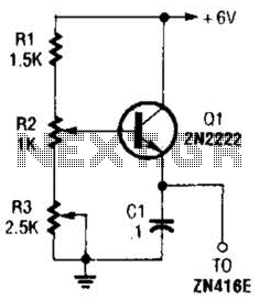
This regulator can be used with a +6-V source to supply the ZN416E low-voltage TRF radio receiver IC with the necessary +1.5 V. R3 sets the output voltage. The circuit utilizes a voltage regulator designed to convert a +6 V...
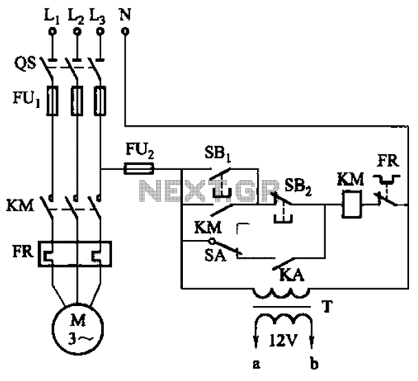
The circuit illustrated in Figure 3-81 employs a transistor delay circuit to facilitate start-stop cycle control. It can operate in both manual and automatic modes. The circuit is primarily governed by the motor run time circuit, which includes transistors...
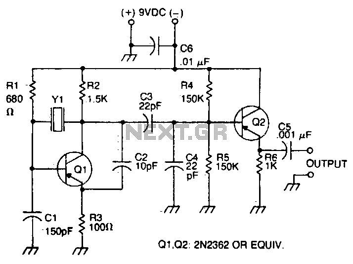
The oscillator transistor is Q1, and the crystal is placed between the collector and base. Feedback is improved by the use of the collector-emitter capacitor C2. Transistor Q2 is used as an output buffer. The circuit described features an oscillator...
The phase shift oscillator produces a sine wave output in the audio frequency range. Resistive feedback from the collector results in negative feedback due to a 180-degree phase inversion from the base to the collector. The three 60-degree RC...
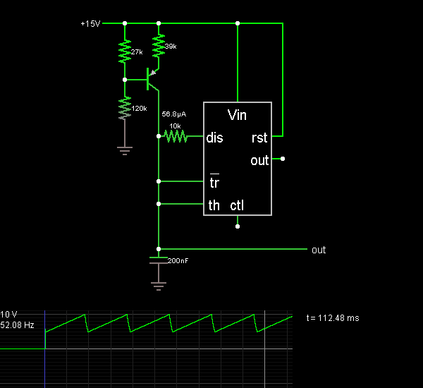
This document presents the 555 Sawtooth Oscillator circuit diagram along with a detailed explanation of its operational principles. An electronic circuit simulator is available to assist in designing the 555 Sawtooth Oscillator circuit and simulating it online for enhanced...
The Wien bridge sine wave oscillator is an oscillator that operates by utilizing positive feedback to return the oscillation output to the input. The key aspect of this circuit is the negative feedback mechanism, which ensures stable oscillation operation....
Warning: include(partials/cookie-banner.php): Failed to open stream: Permission denied in /var/www/html/nextgr/view-circuit.php on line 713
Warning: include(): Failed opening 'partials/cookie-banner.php' for inclusion (include_path='.:/usr/share/php') in /var/www/html/nextgr/view-circuit.php on line 713