
A Low Power Wireless Audio Power Amplifier circuit

This project employs an infrared (IR) transmission system to wirelessly deliver audio signals, making it an effective solution for personal audio experiences in shared environments. The core components of the system include an infrared transmitter, which is connected to the audio output of the television, and a corresponding infrared receiver linked to the loudspeakers.
The infrared transmitter converts the audio signals from the TV into modulated infrared light signals. This modulation is crucial as it allows the audio information to be encoded onto the IR light wave, enabling it to be transmitted over a distance. The design can utilize standard IR LEDs, which emit infrared light that is invisible to the human eye, ensuring that the transmission does not disturb others in the vicinity.
The receiver, typically comprised of an IR photodiode or phototransistor, detects the incoming infrared signals and demodulates them back into audio signals. These audio signals are then amplified and sent to the loudspeakers for playback. The system's effective range of up to 6 meters without lenses is due to the direct line of sight required for infrared transmission; however, the use of lenses and reflectors can significantly enhance the range and focus of the transmitted signal.
In terms of power requirements, the transmitter and receiver circuits can be powered by low-voltage DC sources, making the system energy-efficient. Additionally, the project can be designed to include basic control features, such as volume adjustment at the receiver end, providing users with an intuitive interface to manage their audio experience.
Overall, this infrared audio transmission system represents a practical and innovative approach to personal audio solutions, minimizing the clutter and inconvenience of wired connections while providing flexibility in installation and use.Using this low-cost project one can reproduce audio from TV without disturbing others. It does not use any wire connection between TV and Loud Speaker. In place of a pair of wires, it uses invisible infra-red light to transmit audio signals from TV to Loud speakers, Without using any lens a range of up to 6 meters is possible. Range can be extended by using lenses and reflectors with IR sensors comprising transmitters and receivers..
🔗 External reference
Related Circuits
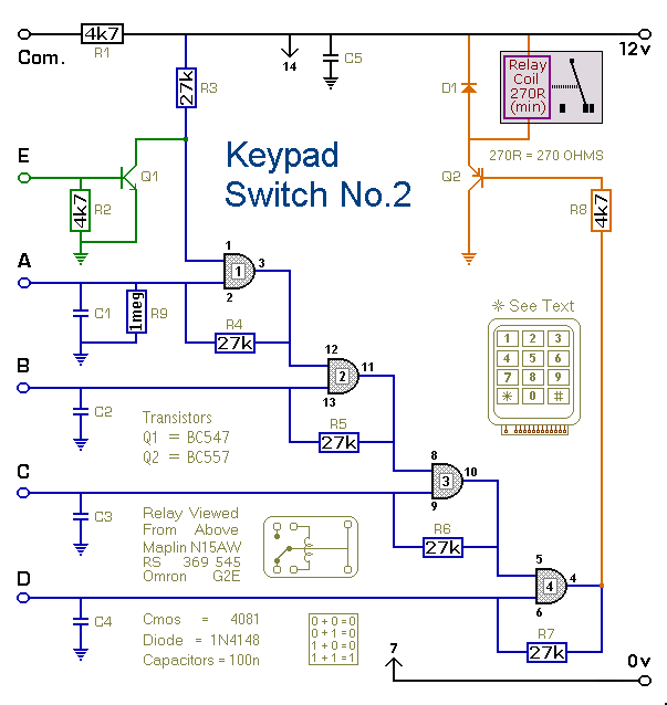
This is a simplified version of the 4-Digit Keypad Controlled Switch. The design has been modified to reduce the complexity of the circuit and the number of components required. Consequently, the code may be somewhat less secure; however, it...
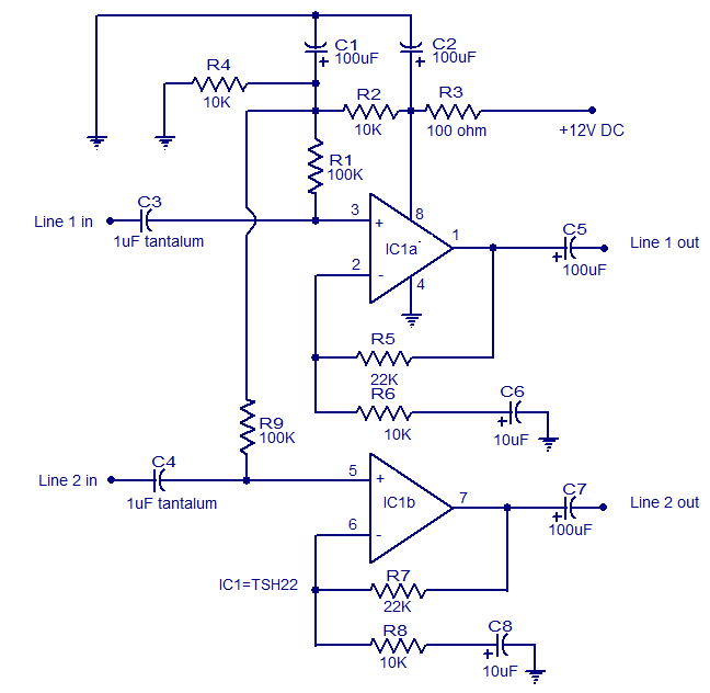
This is the circuit diagram of a two-channel audio line driver utilizing the high-performance dual op-amp IC TSH22 from ST Microelectronics. The IC features a 25 MHz bandwidth, low distortion, and high output current, enabling it to drive medium...
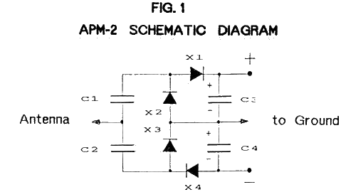
The Ambient Power Module (APM) is a straightforward electronic circuit that, when connected to an antenna and an earth ground, can deliver a low voltage output of up to several milliwatts. An optimal setup involves a long wire antenna...

This circuit design for a low current relay is intended for use in battery-operated electronic devices, with an operating current in microamperes (µA). It utilizes a bistable relay and additional components to enable the relay to function similarly to...
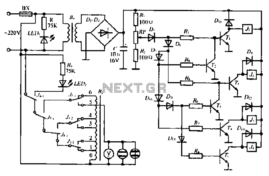
A step-down transformer converts AC 220V to a lower voltage. A diode bridge rectifier and filter capacitor provide a direct current (DC) output, which fluctuates with variations in the grid voltage. A resistive voltage divider is used for sampling....
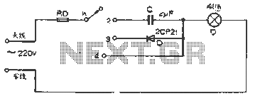
The figure illustrates a basic dimming lights circuit. The light intensity is controlled by a multi-speed control switch, designated as K. When switch K is set to position "1," the lights are turned off. In position "2," the light...