
Wingfoot 813 Circuit Description and Schematic Diagram

The grounded grid amplifier circuit described operates effectively within the specified parameters, ensuring that both RF and filament power are managed correctly. The use of capacitors and inductors in the design provides a robust filtering mechanism that minimizes interference and enhances performance. The design prioritizes safety by incorporating protective elements, such as the RF choke, which safeguards against potential failures that could lead to dangerous voltage levels on the antenna. The tuning components, including the variable capacitor and band switch, allow for fine adjustments to match the amplifier's output to the specific characteristics of the antenna system, ensuring optimal transmission efficiency. Overall, this circuit exemplifies a well-engineered solution for interfacing high-impedance devices with lower impedance loads while maintaining performance and safety standards.The input impedance of a grounded grid amplifier is typically several hundred ohms. Though most vacuum tube transmitters will have no trouble driving such an impedance, solid state transmitters, which are designed to drive loads that are very close to 50 ohms, will usually refuse to drive such a load. The best (and most complicated) solution is to use a tuned matching network on the input. However, a simple 1 to 4 unbalanced to unbalanced transmission line transformer is very easy to make and will lower the input impedance by roughly a factor of four, usually bringing it within range of most solid state transmitters. In this amplifier the input transformer is made by winding seven turns of RG-174 coax or similar small coaxial cable on an FT-50A-61 toroidal core.
If the coaxial cable is not available, 11 turns of #24 enameled magnet wire, bifilar wound, will also work. Click here for a picture of the transformer. In a directly heated cathode grounded-grid circuit it is necessary to allow both the input RF and the filament power to reach the filament/cathode without interfering with each other.
In the circuit shown at right the two 0. 01 uf capacitors permit the input RF from the input matching circuit to reach the filament, while preventing the much lower frequency filament AC from flowing back through the input circuit. At the same time, it is important to keep the input RF from flowing into the filament power transformer.
This is accomplished with a pair of heavy duty RF chokes that are actually wound on the same core. These allow the low frequency heater AC to pass through while blocking the much higher frequency RF. Any residual RF that might have passed through the RF chokes is shorted to ground through the two 0. 02 uf capacitors. The filament transformer provides 10 volts AC at 5 amperes to heat the 813 filament. In an RF amplifier it is necessary to supply DC plate voltage to the tube (about 2000 volts in this case) and at the same time extract the amplified RF that appears at the plate of the tube. In the circuit at right, the R-175 plate RF choke allows the direct current from the plate supply (B+) to pass through it, while preventing the RF on the plate of the tube from flowing back through the plate supply.
At the same time, the 500 pf plate coupling capacitor (at the top in the schematic) permits the RF on the plate to flow though to the output tank circuit while blocking the plate voltage. The 500 pf capacitor at bottom short circuits any residual RF that might have gotten through the plate choke and prevents it from reaching the plate supply.
The small coil in series with the plate lead is a parasitic suppressor, which helps prevent unwanted oscillations. The plate tank circuit is a pi-network that matches the high impedance of the plate to the low impedance of the antenna.
At the same time the circuit filters out undesired harmonics from the output signal. The signal from the plate enters through the 500 pf plate coupling capacitor at the upper left in the schematic. The two 40 pf capacitors and the 220 pf variable capacitor, in combination with the plate tank coil, tune the plate to resonance.
The two 40 pf capacitors are placed in parallel to produce an 80 pf capacitor. This is then placed in series with the 220 pf variable capacitor. The result is effectively a variable capacitor with a maximum capacitance of about 59 pf. This slows the plate tuning rate and makes the amplifier much easier to tune. The band switch varies the inductance of the tank coil, and the 1500 pf load capacitor adjusts the network for the best impedance match. The 2. 5 mH RF choke performs two important functions: If the plate coupling capacitor should fail and short, the RF choke will short circuit the plate supply, hopefully blowing the fuse.
This will prevent the plate voltage from appearing on the antenna, a very dangerous situation. The choke also prevents any DC volta 🔗 External reference
Related Circuits
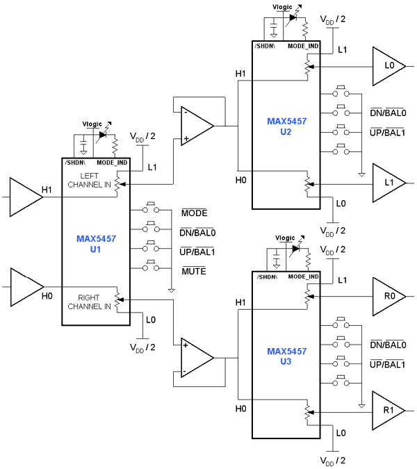
Application circuit using three stereo digital potentiometers to control volume, balance, and fader in a four-speaker configuration with a push-button interface. The application circuit utilizes three stereo digital potentiometers, which are essential components for managing audio levels in a multi-speaker...
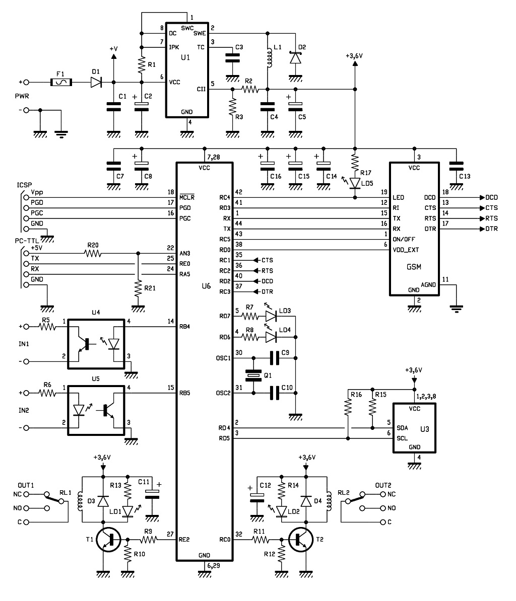
The control of the system is managed by a Microchip PIC18F46K20-I/PT microcontroller, which is programmed with firmware to oversee the activity of the GSM/GPRS module, monitor the logic conditions of two opto-isolated inputs, and send commands to two relays...
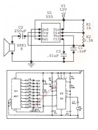
An astable oscillator is constructed using a 555 timer, producing an alarm tone of 1.8 kHz that directly drives a speaker. This fundamental alarm circuit serves as a basis for various other projects in the book. Although the circuit...
Two thoughts on a motion-activated Joule Thief LED bike light. The circuit for switching on and delayed switch-off is simple. The motion-activated Joule Thief LED bike light utilizes a straightforward circuit design that capitalizes on the principles of energy conservation...
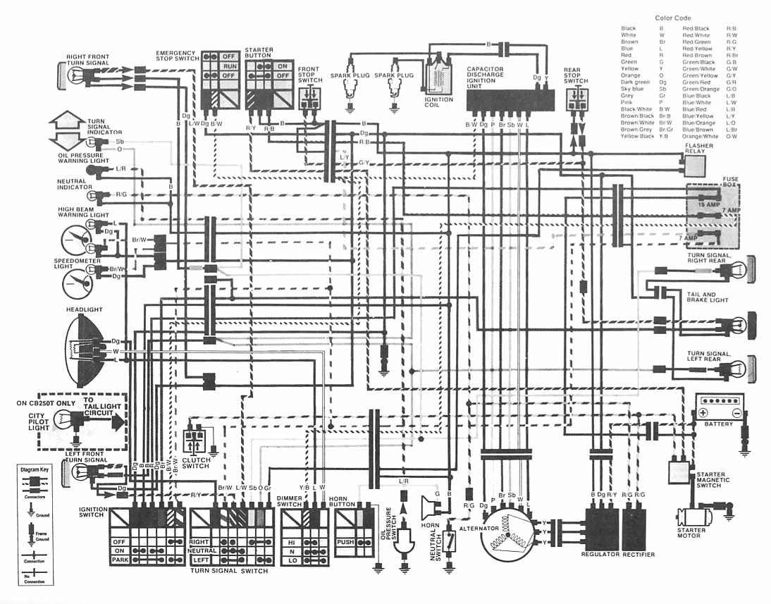
The following image depicts the electrical wiring connection diagram for the Honda Motorcycle CB400 (Hawk II). It illustrates the interconnections between various Honda components, including the turn signal, emergency stop switch, starter button, spark plug, capacitor discharge ignition unit,...
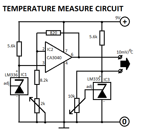
This circuit is designed for Fahrenheit measurements, with the freezing point set at 320°F. At 2120°F, P2 is adjusted to achieve an output voltage of 0.9V. The circuit operates by utilizing a temperature sensor that converts temperature readings into a...