
mosfet tester
The described circuit is an astable multivibrator configuration tailored specifically for testing N-channel MOSFETs, particularly power MOSFETs like the IRF830. The astable multivibrator is a type of oscillator that generates a continuous square wave output without requiring any external triggering. This circuit operates by alternately charging and discharging capacitors, which in turn controls the gate of the MOSFET being tested.
In this configuration, two resistors (R1 and R2) and a timing capacitor (C1) are connected to the MOSFET gate. The choice of resistor and capacitor values determines the frequency of oscillation, allowing for a range of test conditions. The output from the multivibrator can be connected to the gate of the MOSFET, enabling it to switch on and off rapidly. This rapid switching simulates the conditions under which the MOSFET would typically operate in a circuit.
To ensure accurate testing, the circuit may include additional components such as diodes for flyback protection, especially if inductive loads are involved. A power supply is required to provide the necessary voltage for the circuit, and it is crucial to ensure that the supply voltage is within the safe operating limits of the MOSFET being tested.
The output waveform can be monitored using an oscilloscope to verify the switching characteristics of the MOSFET. This includes observing the turn-on and turn-off times, as well as the gate threshold voltage. By adjusting the resistors and capacitors, the user can tailor the test conditions to assess the performance of different MOSFETs under varying frequencies and duty cycles.
Overall, this astable multivibrator-based testing circuit is a practical and efficient tool for evaluating the operational characteristics of power MOSFETs, providing valuable insights into their performance in real-world applications.This is a variation on the astable multivibrator. Circuit was recently developed to test for N-mosfets(the power kind e.g irf830).. 🔗 External reference
Related Circuits
This circuit performs a rapid battery test without requiring an external power supply or costly moving-coil voltmeters. It features two testing ranges: when switch SW1 is configured as indicated in the circuit diagram, the device is capable of testing...
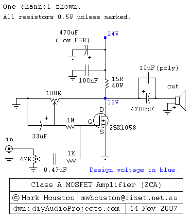
This weblog discusses electronic circuit schematics, PCB design, DIY kits, and electronic project diagrams. It features a simple Class A MOSFET amplifier using the 2SK1058 component. The circuit operates with a 24V supply voltage at high current. It incorporates...
A simple and easy telephone line tester circuit that can be used for testing telephone lines. The telephone line tester circuit is designed to verify the functionality and integrity of telephone lines. It typically comprises a few essential components, including...
The circuit described is suitable for indicating the capacity of a battery using a low-cost electric clock. By connecting a resistor across the battery terminals, the battery discharges at a faster rate than it would with the clock alone....
Logic-1 and logic-0 represent the states of digital signals, where logic-1 corresponds to a high voltage close to Vcc, and logic-0 corresponds to a voltage near neutral or ground. Logic-0 cannot be transformed into logic-1, while logic-1 can revert...
The UTP Cable Tester is designed for multiple applications, primarily to test UTP network cables. It can also assist in identifying the correct cable from a large bundle of similar cables. The circuit can be adapted to test any...