
UTP cabel tester
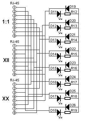
The UTP Cable Tester circuit can be broken down into several key components that work in conjunction to provide effective cable testing capabilities. The signal generator circuit, powered by a 9V battery, utilizes the IC 4060 to produce a low-frequency square wave output. This frequency is essential for driving the LED indicators in a recognizable pattern, allowing users to easily identify the status of the cable being tested.
The output from the IC 4060 is fed into the IC 4017 decade counter, which sequentially activates its outputs based on the incoming clock signal. Each output corresponds to one of the eight LEDs in the display box. The LEDs are arranged in a linear fashion, illuminating in a walking pattern to indicate proper cable continuity. The design ensures that only one LED is lit at any given time, which helps in diagnosing issues such as wire swaps or shorts. The inclusion of a visual indicator on the signal box confirms that the tester is powered and operational.
The RJ-45 connectors are crucial to the tester's functionality, allowing for versatile cable testing. Each connector is designed for specific cable types, ensuring that the tester can accurately assess both straight-through and crossover configurations. The use of diodes and other protective components further enhances the reliability of the circuit, safeguarding it from potential damage caused by incorrect connections.
In summary, the UTP Cable Tester is a practical tool for network technicians, providing essential diagnostics for UTP cables. Its straightforward design, combined with the use of discrete components, allows for effective testing while maintaining ease of use and reliability. The ability to adapt the circuit for various cable types and the inclusion of visual indicators make it a valuable asset in network maintenance and troubleshooting.The UTP Cable Tester can be used for many purposes. Mainly to test a UTP network cables of course. However it can also be used to find the right cable in a large bundle of identical looking cables. In fact the circuit can be used or adapted to test any type of cable of any number of wires, provided that the tester is equipped with the appropriate connectors. The UTP Cable Tester consists of 2 tiny boxes that have to be connected to each end of the cable under test. One of the boxes contains a signal generator, powered by a standard 9V battery. The other box contains 8 LEDs that indicate the cable`s condition. The principle of operation is very simple: A good cable will show a single walking light. However when the lights are lit out of order you`ll know that some wires have been switched in one or both of the connectors.
If one or more lights don`t light you`ll know that one or more wires are cut. If two or more lights light up simultaneously you`ll know that two or more wires are shorted together. This is only a simple tester and therefore it can not detect separated pairs. Even if all pins are connected, showing the expected walking light pattern it does not automatically mean that the pairs are still pairs in the cable.
Separating or mixing pairs will cause network problems on higher speeds and longer cables. The UTP tester will not indicate such fault conditions! Some network adapters and network switches have an auto polarity mode. This means that you may switch the white and coloured wires of a particular twisted pair without causing problems. A cable with wires 1 & 2 switched or 3 & 6 switched will indicate false on the UTP Cable Tester but might still function in some cases.
It is not recommended to rely on the ability of the network adapter and network switch to sense the polarity. When one of the devices is replaced by an other one after a while you may be in trouble. The display box has 3 RJ-45 connectors. The first one, marked 1:1, is intended for testing Straight Through or so called Patch cables. The second one, marked Xll, is used for testing 10baseT and 100baseTX Cross cables. The third one, marked XX, is used for testing 100baseT4 cross cables. The Signal Box is powered by a 9V battery B1 which can be switched on and off by switch S1. Diode D2 protects the circuit in case the battery is connected the wrong way up. Current drain is minimal, approximately 5mA, which ensures quite a long battery life. The IC 4060 generates a low frequency at its output. The exact frequency is not that important, as long as you can identify signals in the wrong order on the Display box.
I choose a frequency of about 3Hz, resulting in a total loop time of approximately 3 seconds. You may change the frequency by changing the value of C1 to suit your own needs. This low frequency is fed to the input of the IC 4017, which is a decade counter. It has 10 outputs, only one of which will be high at any time. Every time the counter receives a low to high transition it advances to set the next output high. It has 10 stages, and we need only 8 LEDs on the Display Box. One of the remaining stages is used to flash a LED on the Signal Box to indicate that it is functioning. The 10th stage is obsolete, and no LEDs will be on during that time. This way a short pause is introduced on the light pattern on the Display Box. I could have used a programmable controller like a PIC16F84 or AT89C1051. The program would be quite simple. I deliberately chose the discrete approach thoug 🔗 External reference
Related Circuits
A passive light-emitting diode output level indication circuit. This circuit utilizes a light-emitting diode (LED) to provide a visual indication of the output level from a given source. The design is characterized by its passive nature, meaning it does not...
A simple remote control tester circuit with a diagram and schematic using the infrared sensor IC TSOP1738. An LED will blink when infrared waves fall on it, indicating the remote control is functioning. The remote control tester circuit utilizes the...
Generate sound or output analog voltages with an Arduino. This guide will demonstrate how to set up a basic digital-to-analog converter. To create a digital-to-analog converter (DAC) using an Arduino, one can utilize the Pulse Width Modulation (PWM) feature available...

The main component of the circuit has been achieved using an integrated circuit (IC) with a significant number of bulk components, primarily capacitors. The internal circuit is designed to output from the differential amplifier using a PNP unipolar configuration,...
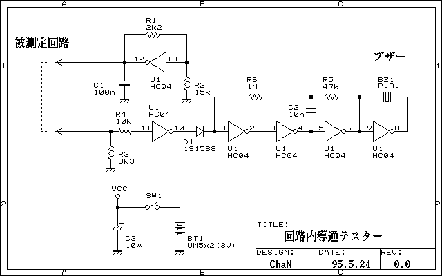
Continuity tester to check continuity in the circuit (Insakittochekka) is. The continuity check over the circuit board wiring that can be checked at a lower voltage semiconductors do not conduct contained in the circuit, you can just check the...
This tester can be used to check the polarity of any power source, and is therefore very useful when installing automotive equipment, alarm systems or anything else you can think of. Because this circuit is so simple and cheap,...