
self powered fast battery tester
The circuit utilizes a simple design that leverages a few key components to facilitate efficient battery testing. The main components typically include resistors, a switch (SW1), and a measurement device, which can be a digital multimeter or an analog meter, depending on the user's preference.
In the first configuration, where SW1 is set to test batteries from 3V to 15V, the circuit connects the battery under test to a voltage divider network formed by the resistors. This voltage divider scales the battery voltage down to a level that is safe for measurement. The output of the voltage divider is then routed to the measurement device, allowing the user to observe the battery voltage directly.
In the second configuration, designed for testing 1.5V cells, the circuit bypasses the voltage divider or utilizes a different resistor value to accommodate the lower voltage. This ensures that the measurement device can accurately read the voltage of the 1.5V battery without damaging the components or providing erroneous readings.
The simplicity of this circuit design makes it highly effective for quick battery tests, eliminating the need for complex setups or expensive equipment. It is particularly useful for hobbyists and professionals alike who require a straightforward solution for assessing battery health and voltage levels efficiently.This circuit runs a fast battery test without the need of power supply or expensive moving-coil voltmeters. It has two ranges: when SW1 is set as shown in the circuit diagram, the device can test 3V to 15V batteries.
When SW1 is switched to the other position, only 1.5V cells can be tested.. 🔗 External reference
Related Circuits
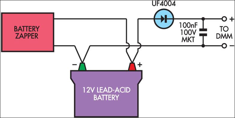
Several readers have inquired about how to determine when the Lead-Acid Battery Zapper has effectively completed the desulphation process. Based on the author's experience, batteries that are responsive to this treatment typically exhibit a notably high peak voltage across...
The battery charger circuit described is straightforward to assemble, requiring only a few inexpensive components and an additional winding on the power transformer (or a separate transformer). Since this charger operates independently of sound reproduction, there are no stringent...
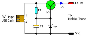
This simple circuit provides a regulated output of 4.7 volts for charging mobile phones. A USB outlet delivers 5 volts DC at a current of 100 mA, which is adequate for slow charging of mobile devices. Most mobile phone...
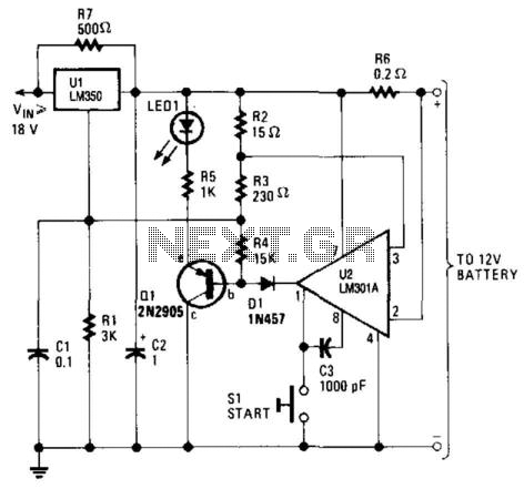
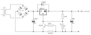
This high-performance charger efficiently charges gelled lead-acid batteries and automatically shuts off upon reaching a full charge. Initially, the charging current is maintained at 2 A; however, as the battery voltage increases, the current gradually decreases. Once the current...
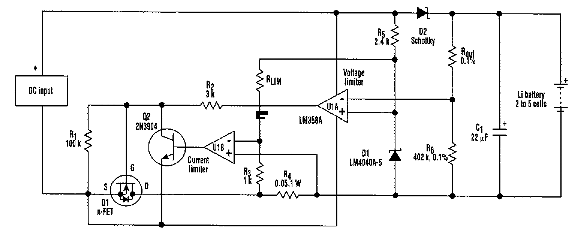
A universal rechargeable lithium battery circuit design, applicable to different battery types and numbers of batteries. This is because both the charger output voltage or current limit setpoint and the maximum charging current can be adjusted by simply changing...
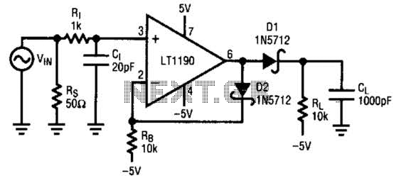
A fast pulse detector can be constructed using this circuit. A very fast input pulse will surpass the amplifier's slew rate, resulting in a prolonged overload recovery time. Implementing some degree of dv/dt limiting on the input can alleviate...