
Motion sensing LED Quantum Bits
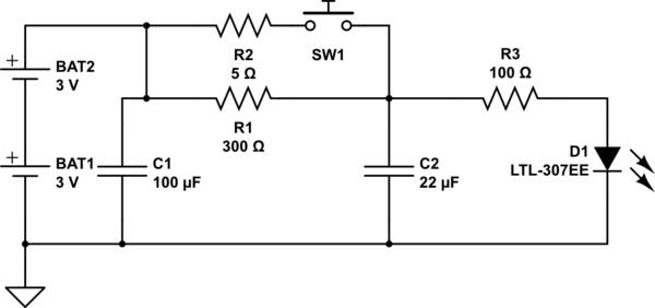
The described circuit utilizes a light-emitting diode (LED) as an output indicator, which is powered under normal conditions through a pair of resistors, R1 and R3. The LED's brightness is maintained at a low level during idle operation, allowing for energy efficiency. The inclusion of SW1, a spring and wire-based accelerometer, serves as an activation switch that responds to motion or acceleration.
Upon activation of SW1, capacitor C2 begins to charge rapidly, influenced by the resistance value of R2. This rapid charging results in a momentary increase in voltage across the LED, causing it to illuminate brightly. The discharge path for C2 is routed through R3, which also limits the current flowing through the LED. The design allows for customization of the LED's brightness and duration of illumination by adjusting the values of R1, R2, and C2.
R1 determines the steady-state brightness of the LED when SW1 is not engaged, while R3 can be modified to set the maximum current that the LED can handle during the brief discharge period. The time for which the LED remains illuminated can be varied by changing the capacitance of C2 and the resistance of R2; larger values will result in a longer illumination duration.
Capacitor C1 plays a crucial role in stabilizing the voltage across the circuit, particularly given the high internal resistance of the battery. It is imperative to select a sufficiently large value for C1 to ensure that the voltage does not drop significantly when SW1 is activated for short intervals. This design consideration is essential for maintaining the reliability and performance of the circuit, particularly in applications where quick activation and response times are required.
Overall, this circuit exemplifies an efficient use of passive components to create a responsive LED indicator system that can be tailored to specific operational parameters through careful selection of resistors and capacitors.The circuit works like this: Normally the LED is powered dimly through R1 and R3. SW1 is the spring and wire based accelerometer I mentioned earlier. When SW1 is closed, C2 quickly charges up (at a rate defined by R2) and is discharged through R3 and the LED. The battery normally has a high internal resistance, and C1 is used to counteract that wh en SW1 is closed. Change R3 to set the max current through the LED. Change R1 to set the normal "steady" brightness of the LED. Change C2 and R2 to vary the length of time the LED is bright. And make C1 large enough that it`s voltage doesn`t change too much when SW1 is closed briefly. 🔗 External reference
Related Circuits
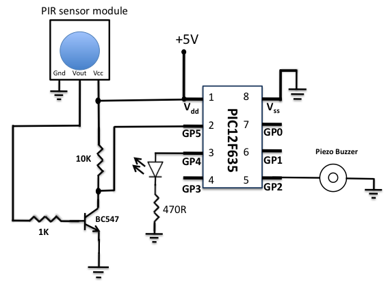
A diode is used in series to drop the voltage to 5.4 V, as the operating voltage for the PIC microcontroller should be below 5.5 V. Additionally, the diode provides protection to the circuit in case of reverse polarity...
The BQ2000 is a programmable, monolithic integrated circuit designed for fast-charge management of nickel cadmium (NiCd), nickel metal-hydride (NiMH), or lithium-ion (Li-Ion) batteries in single or multi-chemistry applications. The BQ2000 detects the battery chemistry and employs optimal charging and...
The simple indicator described in this article can be integrated with any circuit that features an LED bar display powered by a Type LM3914 IC. It ensures that an LED will illuminate when all LEDs driven by the LM3914...
This is a VU meter circuit featuring 10 LEDs. This simple LED VU meter consists of only a few components, yet it serves as an effective indicator for sound levels. The circuit is constructed around an unspecified component. The VU...
The circuit illuminates a high-brightness LED even at a voltage of 0.8V if the battery can supply 93mA at this voltage. The average step-up efficiency from 0.8V to 1.5V is 75%, with a peak efficiency of 83% occurring around...
A phase-locked loop (PLL) is widely utilized in telecommunications, control systems, and various other electronic applications. PLLs can be employed to demodulate frequency-modulated (FM) signals and generate a stable output frequency. A phase-locked loop is an essential feedback control system...
Warning: include(partials/cookie-banner.php): Failed to open stream: Permission denied in /var/www/html/nextgr/view-circuit.php on line 713
Warning: include(): Failed opening 'partials/cookie-banner.php' for inclusion (include_path='.:/usr/share/php') in /var/www/html/nextgr/view-circuit.php on line 713