
motion sensor using pir sensor module
The circuit design incorporates several key components that work together to achieve the desired functionality. The diode, placed in series, ensures that the voltage supplied to the PIC microcontroller remains within safe operating limits, thus preventing damage from excessive voltage. The use of an LM7805 voltage regulator when employing a 9 V battery further stabilizes the voltage to the microcontroller.
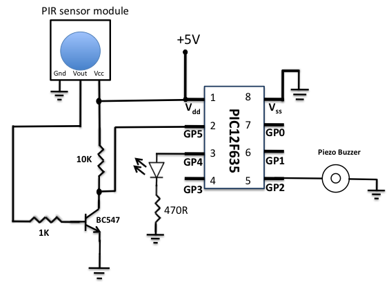
The PIR sensor module is a crucial element, capable of detecting motion within a specified range. Its output is interfaced with the PIC microcontroller to initiate actions based on detected movement. The choice of the BC547 transistor to amplify the sensor's output allows for more robust control over the relay, facilitating the switching of higher loads, such as the white LED or other external devices.
The relay used in this circuit is a DPDT type, which provides versatility in controlling external loads. The spare contacts of the relay can be configured to connect or disconnect various devices, enhancing the circuit's functionality. The inclusion of a current-limiting resistor (R3) ensures that the LED operates within its safe current rating, preventing damage while providing adequate illumination.
The timing capabilities of the SB0061 IC allow for customizable operation durations, making the circuit adaptable for various applications, such as corridor lighting or security systems. The adjustable timing feature enables users to set the desired duration for which the LED remains illuminated after motion is detected, contributing to energy efficiency.
In summary, the described circuit effectively integrates a motion detection system using a PIR sensor, a microcontroller, and a relay to control lighting or other external loads based on detected movement. The design principles employed ensure reliable operation, protection against reverse polarity, and flexibility in application, making it suitable for both security and convenience-oriented implementations.A diode is used in series to drop the voltage down to 5. 4 V as the operating voltage for the PIC microcontroller should be below 5. 5 V. Besides, the diode also provides the protection to the circuit in case of reverse polarity of the power supply. I have tested the circuit with NI-MH rechargeable batteries (that gives 4. 8 V) and it worked, but I r ecommend to use the alkaline batteries (1. 5 V each) for better performance. You can also use a 9 V battery but then you need a LM7805 regulator IC in your circuit. The output of the PIR sensor module is monitored through GP5 (pin 2) of PIC12F635. When the motion is sensed, this output is high at about 3. 3 V (my sensor module has a 3. 3V regulator IC on board). You could still use this voltage as a valid logic high for PIC12F635, but I preferred to use this voltage to drive the base of an NPN transistor (BC547) so that at the collector we will have the full swing of the logic voltages. Now, the microcontroller monitors the voltage at the collector of the transistor. During the normal condition, the transistor is cut off, and the collector output is at logic high (+5 V).
When the motion is sensed, the high output from the sensor module saturates the transistor and the voltage at the collector drops down to logic low. The jumper selection for trigger is at H position, so the sensor output will remain active as long as the motion exists.
Note that the PIC12F635 microcontroller uses the internal clock oscillator at 4. 0 MHz. The MCLR function is disabled and WDT is OFF in this project. Pyroelectric sensor module, developed for human body detection. A PIR detector combined with a fresnel lens are mounted on a compact size PCB together with an analog IC (SB0061) and limited components to form the module. High level output (3. 3V) of pre-settable variable width (5Secs -18 Minutes) is provided. Circuit diagram of the PIR Motion Sensor Light and Switch based on SB0061 shown here can be used for security or corridor lighting in power saving mode.
The 12V DC supply required for the whole circuit can be fed from any standard 12V ac mains adaptor/battery. Working of the circuit is simple and straight forward. When any movement is detected within near 5-6 metres, around 3. 3 Volt is appeared at the base of Transistor T1 and it conducts to fire the next relay driver transistor T2.
As a result, the 12V DPDT relay is energised to power the White LED through current limiting resistor R3. Spare relay contacts can be used as a switch to control any suitable external load. The white LED and the relay remains ON for a duration based on the mono time setting in SB0061, ie from 5 Secs to 18 Minutes.
🔗 External reference
Related Circuits
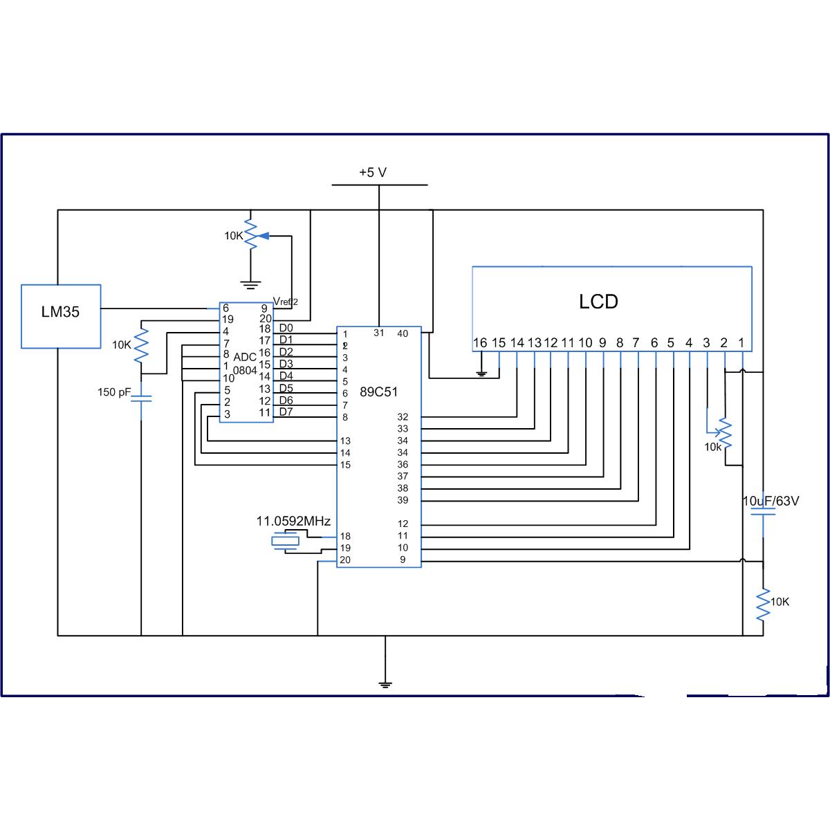
The LM35 series are precision integrated-circuit temperature sensors, whose output voltage is linearly proportional to the Celsius (Centigrade) temperature. The LM35 has an advantage over linear temperature sensors calibrated in Kelvin, as the user is not required to subtract...
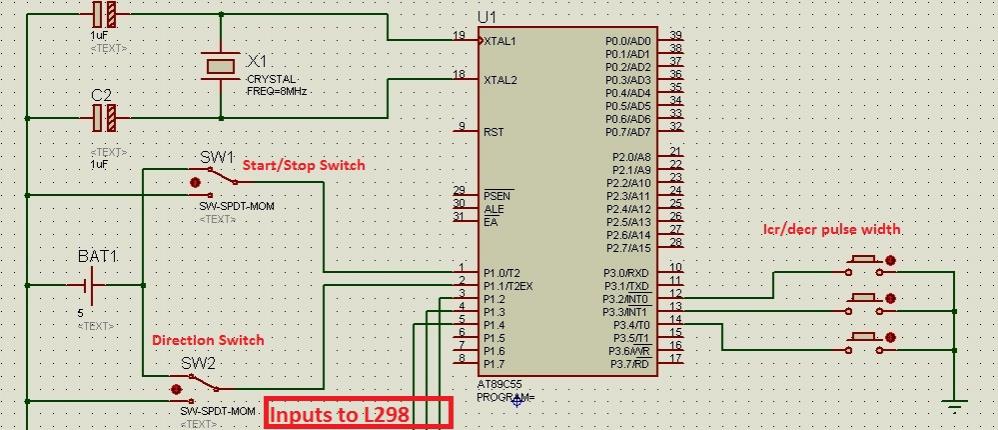
Greetings to all! A new user is exploring microcontrollers and is utilizing the AT89C55WD microcontroller to control an H-Bridge (L298), which subsequently drives a DC motor. The circuits for this setup are... The AT89C55WD microcontroller is an 8-bit microcontroller from...
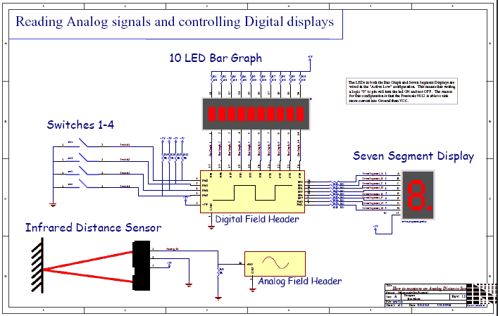
This video demonstrates the process of reading an analog voltage, computing data, and controlling LEDs using a Sharp GP2D12 Infrared (IR) sensor. The PDQ board connects to a host PC via a serial cable, operating at a baud rate...
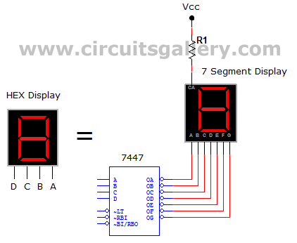
This circuit defines seven levels in a reservoir. The sensed values are connected to an encoder circuit, which consists of a 74148 integrated circuit (IC), functioning as an 8-line to 3-line encoder. The next section features a HEX display,...

The power supply is standard. The 110VAC input connects to connector N17, in series with a power switch SW1, a fuse F1, and the primary coil of transformer T1. The secondary coil of T1 generates 24VAC at 12 Amps,...
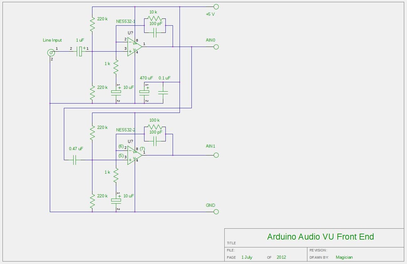
After experimenting with a stereo version of the VU meter described in a previous blog post, a studio-grade VU meter is now being presented. This meter features 24 steps, spaced equally every 3 dB, and covers a wide dynamic...
Warning: include(partials/cookie-banner.php): Failed to open stream: Permission denied in /var/www/html/nextgr/view-circuit.php on line 713
Warning: include(): Failed opening 'partials/cookie-banner.php' for inclusion (include_path='.:/usr/share/php') in /var/www/html/nextgr/view-circuit.php on line 713