
Motor Drivers
The Arduino motor control system utilizes the L298N motor driver chip, which is designed to control the direction and speed of DC motors. The chip operates by receiving control signals from the Arduino, which dictate whether the motors should rotate forward, backward, or stop. The L298N can control two motors simultaneously, making it suitable for various applications including robotics and automation.
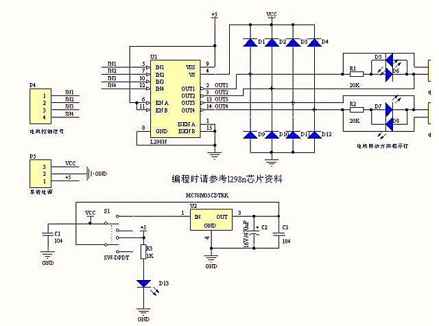
The circuit board layout typically includes input pins connected to the Arduino, output pins for the motors, and a power supply input. The heat sink attached to the L298N chip is crucial for dissipating heat generated during operation, especially when driving high-current motors. The inclusion of diodes in the circuit is essential for protecting the driver chip from voltage spikes caused by back EMF when the motors are switched off. This back EMF can create damaging voltage levels that could potentially harm the driver circuitry.
The presence of LEDs on the output side serves a dual purpose; they not only indicate motor activity but also provide visual feedback regarding the direction of current flow, enhancing the diagnostic capabilities of the system. The +5 volt regulator (MC78M05) ensures that the L298N chip receives a stable voltage supply, which is critical for reliable operation.
Overall, this motor driver setup allows for effective control of DC motors through an Arduino platform, providing a practical solution for projects that require motorized movement.Arduino can drive many kinds of motors. But the low-power signals from Arduino need to control high-power circuits to run the actual motors. Here we will give examples of ways that Arduino can control different types of motors of different sizes. A Motor Driver will usually be a circuit board with several electronics components on it, including a
high-power motor driver chip or some power transistors. (Examples Here:) Boards like this cost about $10 to $15 these days. Here`s an example of an Arduino "Shield" that plugs on top of an Arduino. This uses a motor driver chip L298N which we will detail more about later. Details of operation of the L298N Arduino Motor Driver Shield are HERE: This includes a heat sink for the L298N chip, allowing higher currents. It is also less expensive than a shield version. Often it can be mounted near the motors 2 DC Motors may be connected to the outputs on the right. Arduino controls the inputs so that the motor terminals are connected to Ground or Vcc (Motor Power Supply).
So voltage can be applied in either direction through the motors, or both terminals can be connected to Ground to stop. Note the measures taken here to control "Back EMF" and "power supply noise" as mentioned in the tutorial (DC Motors).
There are 8 diodes that are connected from the motor outputs to ground and the motor power supply. These are to limit or "snub" the back EMF voltages that otherwise would damage the chip. The diodes on the right side are LEDs that light up when the motors are powered and indicate what direction the current is flowing. There is also a +5 volt regulator chip (MC78M05) which supplies +5 volts to the L298N chip. 🔗 External reference
Related Circuits
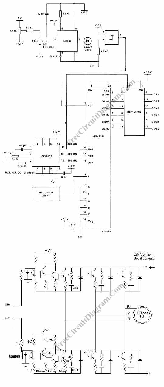
Controlling the speed of a three-phase AC motor is achieved by regulating the frequency of the power supply, as the motor operates in synchronization with the line. To control the speed of a three-phase AC motor, it is essential to...
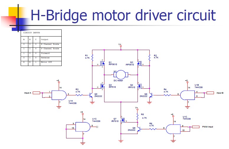
An H-bridge motor driver circuit is designed to control a DC motor. By using a low signal, such as a 5-volt signal, the circuit enables the program to manage the motor, which operates on a higher power supply. The H-bridge...

1998 Ford Escort Blower Motor Wiring Diagram. The 1998 Ford Escort blower motor wiring diagram provides essential information for understanding the electrical connections and components involved in the operation of the vehicle's heating and ventilation system. This diagram typically...
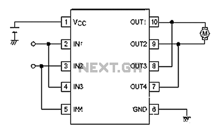
A simple motor control project for forward and backward drive can be implemented using the LB1948M motor driver IC, which features two channels for motor control. The LB1948M is an ideal choice for 12V motor drive systems and can...

This circuit has a long history, originating from an idea by Rich Piotter and later refined by Wilf Rigter and Bruce Robinson. The final result does not include the necessary motor drivers, which are typically H-bridge based, but presents...
To achieve a low-cost, accurate, and simple position control system, a stepper motor can be utilized. A circuit designed to drive the motor should be mounted in proximity to the motor itself. Stepper motors are widely employed in applications requiring...