
3 Phase AC Motor Speed Control

To control the speed of a three-phase AC motor, it is essential to utilize a variable frequency drive (VFD). The VFD adjusts the frequency and voltage supplied to the motor, allowing for precise control over its speed and torque characteristics. In a typical setup, the VFD receives input from a control system, which can include sensors and user interfaces for setting desired operational parameters.
The VFD comprises several key components: a rectifier, a DC bus, and an inverter. The rectifier converts the incoming AC voltage from the power line into DC voltage. This DC voltage is then smoothed and stored in the DC bus. The inverter takes this DC voltage and converts it back into AC voltage at the desired frequency and amplitude, which is then supplied to the motor.
To achieve effective speed control, the VFD employs pulse-width modulation (PWM) techniques. By varying the width of the pulses in the output waveform, the effective voltage and frequency delivered to the motor can be adjusted. This method not only allows for smooth acceleration and deceleration but also enhances energy efficiency by reducing power consumption during low-load conditions.
Additionally, feedback mechanisms, such as encoders or tachometers, can be integrated into the system to provide real-time data on motor speed and position. This feedback can be utilized by the VFD to make dynamic adjustments, ensuring optimal performance and stability of the motor under varying load conditions.
Overall, the implementation of a variable frequency drive for controlling a three-phase AC motor facilitates enhanced operational flexibility, energy savings, and improved performance in various industrial applications.Controlling the speed of three phase ac motor is done by controlling the frequency of the power line supply,? since the motor is synchronized with the line. 🔗 External reference
Related Circuits
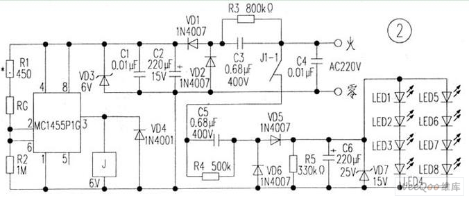
The circuit is depicted in Figure 1, while the electrical schematic diagram is presented in Figure 2. The AC voltage of 220V is reduced by components C3 and R3. The diodes VD1 and VD2 rectify the voltage, and capacitors...
DC motors can be operated remotely using controls transmitted via an RF module. This circuit employs an RF module to manage DC motors through a motor driver integrated circuit (IC) L293D. Transmission is initiated by setting pin 14 (TE,...
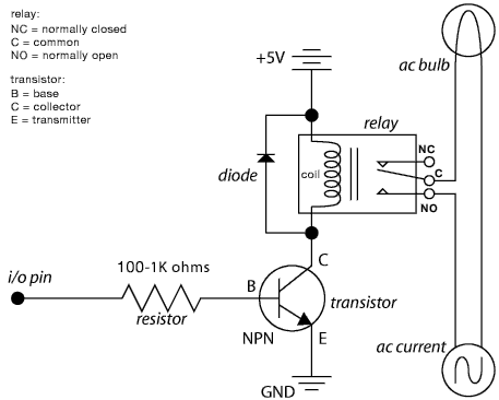
The schematic illustrates the Relay Wiring Circuit Diagram used to control an air conditioner or other high-current devices via a microcontroller. The relay wiring circuit serves as an interface between low-voltage microcontroller signals and high-voltage appliances, such as air conditioners....
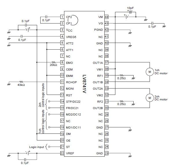
The circuit diagram illustrates an electronic project that requires a few external electronic components. The PWM current-control stepping motor driver IC can provide a maximum output current of up to 1.5 amperes. The configuration settings for the PWM current-control...
The initial PIC program utilizing the C language demonstrates how to blink a single LED using a PIC microcontroller with a C program. This serves as an introduction to C programming for PIC microcontrollers. The circuit for blinking an LED...
A Darlington connection-type transistor is utilized for driving the coil. In this configuration, two stages of transistors are connected in series, resulting in a high current gain, where the "hfe" of the Darlington transistor is the product of the...